Tag Archives: Tip

Tip: what to do when your text becomes empty rectangles

Dear person who used the search terms “writing has become empty rectangle in cad” and “autocad text has become an empty rectangle” on this blog, I suspect you probably have a drawing where QTEXT has been turned on. To fix this, enter QTEXT at the command prompt, set it to OFF, and if the problem doesn’t go away by itself then issue the REGENALL command.

Pedantic note: the command name is QTEXT, but this controls a system variable called QTEXTMODE. QTEXT OFF is equivalent to both SETVAR QTEXTMODE 0 and just QTEXTMODE 0. In LISP it would be (setvar “QTEXTMODE” 0).

This tip applies to all AutoCAD releases and variants you’re likely to run. Because BricsCAD has a high degree of command-line compatibility with AutoCAD, it applies to BricsCAD too. The same may apply to other AutoCAD-compatible applications.

Tip – making your 3D controller work sensibly in BricsCAD

This tip applies to BricsCAD V14 to V18 inclusive, and possibly other versions too.

BricsCAD automatically works with a 3D “mouse” (e.g. 3DConnexion SpaceNavigator controller), and due to the generally excellent performance of BricsCAD in 3D, it works very smoothly and is a real productivity boon for 3D work. If you don’t already have one and you work in 3D, it’s well worth spending a fraction of the money you saved by switching to BricsCAD to get hold of one.

Unfortunately, the way BricsCAD reacts to use of this device fails to lock the horizon by default. This means it does not keep the vertical axis vertical, so unless you have an exceptionally light and skilled touch, you will soon have your model skewed, upside down and/or flopping around all over the place.

OK, this may be a silly default setting, but how do you change it? Read on.

Method 1

Press the left button on your controller. If you’re lucky, you will see the 3dxWare Panel. (I’m not seeing it in V18 so maybe I need a driver update). Use the Button Configuration tab and change it from “All Applications” to “BricsCAD”, then it should show as:

  • L: BricsCAD Default Menu
  • R: Fit

Picking the controller’s left button in BricsCAD after doing this brings up a context menu containing a Lock Horizon option.


Once you turn this on, the controller will work as expected.

Method 2

If you don’t have those options available to you when you pick the controller’s left button and you’re comfortable messing around in the Registry (the usual caveats apply here), you can fix it up.

First close BricsCAD. Now start REGEDIT and search for the 3dMouseMenu section, e.g. HKEY_CURRENT_USER\Software\Bricsys\BricsCAD\V18x64\en_US\Profiles\3D Modeling\3dMouseMenu. Under there is a LockHorizon value: change that from 0 to 1. Next time you start BricsCAD, the controller should work as expected. If therre are multiple user profiles, you will need to repeat this process for each profile.

Method 3

If you don’t have rights to use REGEDIT or you don’t feel comfortable doing so, you can achieve the same result by exporting and importing a user profile, with a little bit of text editing inbetween.

  • Close BricsCAD
  • Start the User Profile Manager (e.g. Start > All Programs > Bricsys > BricsCAD V18 (x64) en_US > V18×64 User Profile Manager
  • Choose a user profile and export it
  • Manually edit the resultant .arg using a text editor (e.g. Notepad) and change the appropriate line under 3dMouseMenu to “LockHorizon”=dword:00000001
  • If that section doesn’t exist, add it as follows (ensuring you use the right version information, e.g. V16x64 in place of V18x64):
    [HKEY_CURRENT_USER\Software\Bricsys\BricsCAD\V18x64\en_US\Profiles\3D Modeling\3dMouseMenu]
    "Rotate"=dword:00000001
    "PanZoom"=dword:00000001
    "LockHorizon"=dword:00000001
    "RotCenterModeAuto"=dword:00000001
    "RotCenterModeSelected"=dword:00000001
    "Speed"=dword:00000001
    "3dMouseMode"=dword:00000000
    "RotCenterVis"=dword:00000002
  • Import the edited .arg – you’ll have to provide a different name to any existing profile. Don’t worry, you can rename and delete profiles later as required.
  • Set that profile current
  • Start BricsCAD

You can do the same from within BricsCAD using Tools > User Profile Manager, but as you need to restart BricsCAD anyway before the change takes effect, you may as well do the above.

AutoCAD 2018.0.2 arrives

AutoCAD 2018.0.1 is dead, long live 2018.0.2!

Here’s the readme.
Here’s the 64-bit direct link.
Here’s the 32-bit direct link.

This supposedly fixes stuff that 2018.0.1 broke, such as the signed VLX thing. Will this one break other stuff? I guess we’ll find out.

AutoCAD 2018.0.1 mystery deepens with silent withdrawal

As I mentioned earlier, the release of AutoCAD 2018 was followed almost instantaneously by the first update, 2018.0.1. At the time of writing, there was no official information about this update. Some information was later made available, but questions remained.

Now the update has been silently withdrawn. Go to Autodesk Account > Management > AutoCAD > Downloads > Updates & Add-ons and you will no longer see this:

The infamous Autodesk desktop app also shows no sign of this update. So why has it been withdrawn? Autodesk isn’t saying, but thanks to Jimmy Bergmark, we know that installing the 2018.0.1 update re-introduces a bug from AutoCAD 2016 (pre SP1) where signed VLX files don’t load. This means various 3rd party applications won’t load if the developers have done the Autodesk-recommended right thing by digitally signing their code.

If you’re a developer and want to test your code under the different versions, these direct links still work at the time of writing:

If you’re not sure whether or not you have 2018.0.1 installed, the About command will show you.

You can also check for this under program control by inspecting the system variable _VERNUM. In AutoCAD, it’s “O.49.0.0” before the patch and “O.61.0.0” after. I don’t know about LT, and I don’t know about the situation with verticals. Do they incorporate the 2018.0.1 fixes? How about the VLX bug? Should users who have applied this update uninstall it? Is this going to be done automatically or by Autodesk desktop app? How should users manually revert to the pre-2018.0.1 state if they need to load applications that use signed VLX files?

I think it’s fair to say that Autodesk’s management of this update has been a disaster. This is just one in a long line of AutoCAD update screw-ups going back decades. It proves comprehensively that continuous updates from Autodesk are a non-starter.

Autodesk can’t be trusted avoid breaking things with its updates. It can’t be trusted to effectively communicate about the updates. It can’t be trusted to provide fixes for its broken fixes. It can’t be trusted to provide an automated update mechanism that doesn’t hog your resources or one that works properly.

The AutoCAD 2018 install inflicts the execrable Autodesk desktop app on your systems without asking, which in itself is a betrayal of trust. I recommend you uninstall it immediately after all Autodesk installs. You will need to right-click the app tray icon and use the Exit option before you can uninstall it using Add or Remove Programs.

Autodesk needs your trust to make its continuous update idea work. Autodesk doesn’t have that trust. Autodesk doesn’t come close to deserving it.

Autodesk updates Design Review

Despite the previously announced end-of-active-life for Design Review (Autodesk’s DWF viewer), there is now a new release available. This wasn’t supposed to happen, because we should all now be using cloud-based solutions.

A new version of DWG TrueView was needed to deal with the new DWG 2018 format, and one knock-on effect is that a new Design Review was needed to be compatible with DWG TrueView 2018.  It’s still only 32-bit, so it appears to be a matter of Autodesk just touching it up enough to keep it compatible.

Interestingly, the new Design Review is not called 2018. Here’s where to find it:

On the bloatware theme, if there’s a particular reason this download (421 MB) is over eight times the size of its predecessor (49 MB), it’s not readily apparent.  The installed application is 212 MB, so it’s all a bit mysterious.

The downloaded executable is a WinZip self-extractor. If you’re a CAD Manager, there’s no point in having the unzip happen 100 times for 100 users when it could happen just once, so you’ll want to grab the extracted files and install from those. This installer makes that difficult, but not impossible. If you want to do that, read on. If you’re just installing it once, skip the next two paragraphs.

Running SetupDesignReview.exe (note the lack of version information), the extraction started but I couldn’t find out where it was extracting to. I eventually found it in the folder %Temp%\XXX.tmp, where XXX is a random name, e.g. _AID0D9. This folder gets automatically erased on completion or cancel, so what you need to do is run SetupDesignReview.exe once, wait for the unzipping to finish but don’t go ahead with the install, copy the %Temp%\XXX.tmp folder elsewhere, then cancel the initial installation. You can then run as many installations as you like using the extracted files.

It would be useful to have these things documented. The Installation Help, System Requirements and Readme links in the installer all rather unhelpfully point to a generic Knowledge Network search.

The install proper will uninstall Design Review 2013 without asking, which is antisocial. For example, if you wanted to keep using HP Instant Printing (not supported in the new release), this installation would mess you up. In my case it also threw up an error during that uninstall, although it still seemed to go through with it.

Note there’s no sign of a release number. The only versioning I can find is in Help > About, with a build version of 14.0.0.177. When you run it, you’ll notice that it hasn’t had the UI of Doom treatment, so it looks like a cut-down AutoCAD from a few releases ago. Not a bad thing.

How about the product itself? Seems to work OK. If you go to open something, it will show you DWG files as well as DWF(x) files. What happens if you try to open a DWG file? This.

Everybody familiar with versioning knows you never put “the latest version” on anything because it’s meaningless. I was once told about a Head Drafter in the early CAD days who had special stamps made up to stamp paper plots with THIS IS THE LATEST VERSION OF THIS DRAWING. The above message is about that smart.

What happens when you pick the Learn More button? Nothing. So I learned nothing.

Anything else? Well, on my system, it takes about twice as long to start up this simple DWF viewer than it does to start up a full-blown CAD application. Want to take a guess at which application I mean?

Can’t complain too much. This product is free, Autodesk is still providing it and still making efforts to keep it up to date. Props for that much, at least.

AutoCAD 2018.0.1 mystery partially resolved but questions remain

As I mentioned earlier, the release of AutoCAD 2018 was followed almost instantaneously by the first update, 2018.0.1. At the time of writing, there was no official information about this update. Some information is now available, but more questions have arisen.

If, like me, you don’t/won’t/can’t have Autodesk desktop app running on your systems, the only current official way to get at the download is using Autodesk Account (but read the whole of this post before you go there). That’s also how you get at information about the update. Go to Management > AutoCAD > Downloads > Updates & Add-ons. From there, it’s not obvious how to get the information, but it’s under More options.

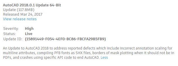
From there, pick View Details. This will show you the following information (after you pick More):

As you can see, the severity is considered high. If you pick View release notes, you can see the readme, or you can go straight to it if you have this direct link. Here are the fixes described in the readme:

  • Occasional crashes when ending an AutoCAD session using specific API code no longer occur.
  • Publishing annotative multiline attributes no longer results in incorrect annotative scaling.
  • PFB fonts can now be compiled successfully as SHX files.
  • The border of a mask is no longer plotted in PDFs when “Lines Merge” is turned on.

Although it would be easy to have a go at Autodesk for shipping a product that needs fixing within hours of release, that wouldn’t be entirely fair. No software is flawless. Stuff happens, and the sooner fixes are provided to resolve that stuff, the better. So I commend Autodesk for getting this fix out quickly.

That doesn’t mean Autodesk is blameless, though. Read on.

First, the way the information about this update was (or wasn’t) disseminated was sub-optimal. It has required too much prodding and guesswork to get to the point we are now, and we’re still not where we should be.

Next, there’s scant information in the readme. I don’t see any documented way of including this fix in a deployment, for example. That means it’s not possible to create a one-step automated install without resorting to trickery.

Further, this update isn’t available on the main Autodesk site. It needs to be. Even if you know the version number to look for, a search at autodesk.com will come up blank:

Using the Autodesk Knowledge Network Download Finder won’t help, either:

Fortunately, these direct links appear to work:

This brings me to my fourth point of criticism. See that the 64-bit executable has “r2” on it? The one I downloaded on 23 March doesn’t. The 64-bit executables are similar in size to each other but the binary content is different. The 32-bit 2018.0.1 has a date of 22 March and the 64-bit 2018.0.1 r2 has a date of 24 March. So it looks like the patch has been patched, at least for 64-bit users.

Information on this patch-patch is non-existent. Should somebody who downloaded and applied the 64-bit 2018.0.1, download and apply 2018.0.1 r2? Will that work? Do they need to uninstall 2018.0.1 first? How should they do that? Will the 32-bit 2018.0.1 also be updated to r2? Should those users hang off a few days to avoid wasting time or go ahead with what’s there now?

Over to you, Autodesk.

AutoCAD 2018 – disable InfoCenter

Here’s another AutoCAD 2018 download, just in case you haven’t had enough.

If you want to disable AutoCAD’s InfoCenter (and you should, unless have a specific reason for keeping it – here’s why), go get the updated download from uber-expert Owen Wengerd’s ManuSoft Freebies page. It works for AutoCAD and AutoCAD LT.

Script for creating AutoCAD Classic workspace

Edwin Prakaso at the excellent CAD Notes blog has done something that, in hindsight, is blindingly obvious but nevertheless very useful to a multitude of people. He’s written a simple script file that sets up the Classic workspace (or something close to it). It works in any recent AutoCAD or AutoCAD LT. Here’s the blog post:

AutoCAD Script to Create Classic Workspace Automatically

Edwin uses Microsoft OneDrive to store the script file, so if your workplace restricts access to Cloud storage you might need to download it at home.

I’ve added a reference to this script to my post AutoCAD 2017 – Putting things back to “normal”.

Undo, U, Redo, Erase, Oops differences explained

It’s been a while since I posted any beginners’ tips, so here goes.

There are several commands in AutoCAD to do with reversing things you’ve done. They are in some cases subtly different and this can confuse newcomers. Here’s what they do:

  • U – reverses the last command you used.
  • Redo – reverses the last U or Undo operation you performed, if that’s the last thing you did.
  • Undo – displays a set of command options that allow greater control over undoing things. (This is rarely used directly by a user, and is more of a programmer’s tool, so I won’t be going into any detail).
  • Erase – removes from the drawing an object or set of objects as selected by the user.
  • Oops – reverses the last Erase command, even if you have done other things in the meantime. (It also reverses erasures performed by the Wblock command, but such reversal is rarely needed these days).

Note that many commands also have an Undo subcommand  which is different again from all of the above. For example, start the Line command, pick a few points, then enter Undo while still in the command. Just the last segment will be removed, and you can carry on picking more points. Most subcommands can be abbreviated, and this is true of the Undo subcommand within the Line command. While still in the Line command, enter U and this will have the same effect as entering Undo in full (or the other possible abbreviations Un and Und).

This is not the case when entering full command names; entering U and Undo at the command prompt will do different things, although command line auto-complete can confuse matters further depending on your settings. I’ll ignore that for the sake of brevity.

Let’s go through a command sequence that uses all of these things.

  • Enter the Line command (type LINE and hit [Enter]). Pick 6 points to create 5 lines but don’t hit [Enter] yet. While still in the Line command, enter Undo (UNDO [Enter]). This will use the Undo subcommand of Line to undo the last drawn line segment, leaving 4 lines. Pick another 2 points, leaving a total of 6 lines. While still in the Line command, enter U. This will undo the last drawn line segment, leaving 5 lines. Hit [Enter] to finish the Line command.
  • Enter the Line command, pick 4 points to draw 3 lines and hit Enter to finish the command.
  • Enter the U command. The effects of the last command (Line) will be undone, removing all 3 of the lines created by it.
  • Enter the Redo command. The U command is reversed, restoring the 3 lines.
  • Enter the Undo command. This will give you a few options, but the default is the number of steps to undo. Type 2 [Enter] and the last 2 commands will be undone (ignoring the U/Redo), removing the set of 3 lines and the set of 5 lines.
  • Enter the Redo command. The Undo command is reversed, restoring both the 5 lines and the 3 lines.*
  • Enter the Erase command. Select one line from the first group and two from the second, then hit [Enter] to finish the command and those 3 lines go away.
  • Enter the Move command. Select the remaining 2 lines from the first group, hit [Enter] to finish the selection process and pick two points slightly apart to move the lines a short distance.
  • Enter the Oops command. The 3 lines removed by the Erase command are restored, but note that the effects of the Move command are unaffected. If you had used the U command twice to restore the erased lines, the Move command would also have been reversed.

Clear as mud? There are other possible complications depending on various settings, and there are various user interface options for invoking the commands that I haven’t discussed, but this will do to explain the basics.

* The information in this post applies to any AutoCAD from the last 30 years, but as the command set in BricsCAD is almost identical, it can be used for BricsCAD too. Mostly. There is one exception; if you use Undo to perform several undo steps at once, then follow that with a Redo, only one undo step at a time will be reversed. If you want to redo everything, you will need to hold your finger on the Enter key to repeat the Redo command until it runs out of things to redo. Depending on what you want to do, this can either be very handy or rather inconvenient.

The best thing about AutoCAD 2017.1 is…

…the fact that one of the Express Tools finally got an update. Not just a minor maintenance tickle or mere absorption into the core code, either. A real update, resulting in not only bug fixes but genuinely useful improvements in functionality.

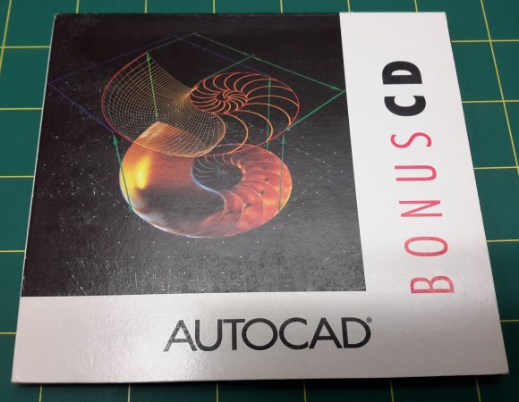
A little background on Express Tools might help put this into context. The history goes back to 1992 and AutoCAD Release 12. In addition to an impressively full set of paper manuals, people with Release 12 (great value at US$500 to upgrade from any earlier release) obtained a Bonus CD containing 2605 files of free add-on goodness. Fonts, LISP, DOS and Unix utilities, sample drawings, demos, all sorts of stuff. Remember that just popping on the web to grab that sort of thing wasn’t really an option at the time, so this CD was quite a big deal.

autocadrelease12bonuscdcase

Release 13 didn’t have an equivalent CD (although it had many other things – most of them bugs), but with Release 14 in 1997 there was a concerted effort to add extra value. A program was put in place to produce a set of bonus stuff, partially developed by external parties. Unlike the Release 12 material, the Release 14 Bonus Tools were (kind of) incorporated into the main product, although they remained unsupported:

Although we put a great deal of effort into making sure the Bonus Tools are free of problems, they are not officially supported by Autodesk. We do not guarantee that the results are 100% error free.
 
To use the bonus tools, choose the Full installation option or select Bonus and Batch Plotting during a custom installation. The installation program places the bonus files in the BONUS\CADTOOLS directory and puts that directory in the Support File Search Path. The installation program also appends your ACADR14.LSP and ACAD.MNL files to ensure the proper loading of the bonus support file AC_BONUS.LSP and menu file AC_BONUS.MNU.

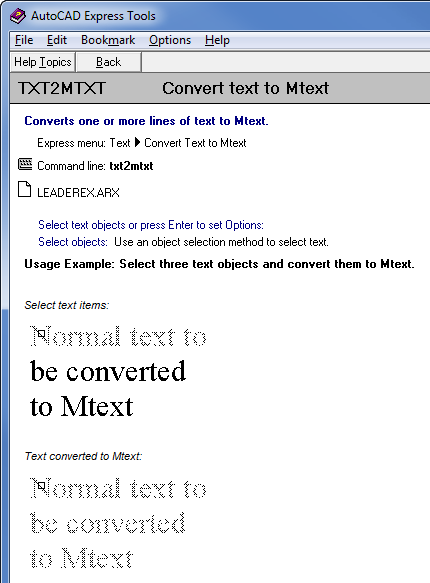
A lot of the things we now take for granted in AutoCAD were born as a result of this initiative. With AutoCAD 2000, Bonus Tools were renamed as Express Tools and some R14 Bonus Tools were removed while others were added to the core product. Several more features were added to an already handy collection, including TXT2MTXT:

autocad2000txt2mtxthelp

The history of Express Tools has been less illustrious since that high point. Autodesk made an ill-advised attempt to make money from them by removing them from AutoCAD 2000i and 2002 and first of all making them available only to VIP/Subscription (now called maintenance) customers as a carrot, then offering them for sale as AutoCAD Express Tools, Vol 1-9. That little business venture was always doomed to fail, and you can still find many sets of instructions allowing people with AutoCAD 2000 to carry across their Express Tools to 2000i and 2002.

Since then, other than some commands being absorbed into the core, it has been “maintenance mode” for Express Tools. This means the code just gets recompiled when necessary and very little actual maintenance goes on. As a result, some 20th Century bugs live on to this day.

Enough history! So what is this best thing? As a byproduct of improvements to PDFImport, the TXT2MTXT command was redone. Not much about this gets mentioned in the readme, but a whole bunch of very good things happened to this seemingly simple command (main source AutoCAD 2017.1 Preview Guide):

  • You can select Mtext objects in addition to Text objects.
  • A Settings option on the Command line displays the Text to MText Settings dialog. In the past you had to press Enter at the start of the command to see the dialog box.
  • Character codes translate correctly between Text and Mtext (e.g. text underlining appeared as %%U when converted to Mtext).
  • The “Select objects” prompt adheres to standard error checking and messaging. For example, objects on locked layers are filtered from the selection set.
  • Justification (Top left, Top center, Top right) is inferred for the Mtext object being created based on the positioning of the text objects in the drawing instead of always using Top left justification. When no justification can be logically inferred, it defaults to top-left.
  • Numbered and lettered list formatting is inferred when the word-wrap text box is checked. If a line starts with one or two characters followed by a period and up to 10 spaces, list formatting will be applied automatically.
  • The top-down sorting order is relative to the current UCS and sorting is left-to-right when text objects are collinear. When multiple text objects are collinear, they are treated as if on the same line with a space between them.
  • A new Settings option enables you to force uniform line spacing or maintain existing line spacing.
  • Various bugs are fixed that caused unexpected results when in a non-WCS UCS.
  • An option was added to the Settings dialog box to not combine selection into a single mtext objects (converts text object to mtext without combining).

That last item alone could be a huge time-saver. If you need to convert 100 text items to mtext (e.g. for background masking reasons), you can now use the command once rather than 100 times. Sure, there are LISP routines to do this (I’ve written some myself), but incorporating it into the core product makes things easier for large numbers of people.

It would not be a bad idea for Autodesk to go through all of the Express Tools looking for similar bug fixes and improvement opportunities. Instead of occasional ad-hoc drip-by-drip adoption of an Express Tool or two into the core, I propose that a special project be undertaken to go through the whole lot, fixing and improving them all. Once done, add them all to the supported functionality of the product, along with any related functionality that makes itself apparent during the overhaul.

Such a project strikes me as something relatively easy to do that would go down very well among customers. Or how about some totally new stuff? Express Tools 2018 – The Next Generation?

How to download Autodesk software without the Akamai download manager

Note: this post is now out of date. AVA no longer provides the facility mentioned here. Instead, it tries (and fails) to be clever.

For reasons beyond my understanding, Autodesk chooses to make life difficult for customers and prospective customers who want to download its products by imposing the use of a download manager (DLM) by Akamai. You really don’t want to let such a thing loose on your system even if it works, for reasons that have been explained in previous posts.

Until a couple of years ago, Autodesk allowed prospective customers to get at a direct download link after jumping through a few hoops and ignoring a bunch of bullshit warnings, but in recent times even that small measure of semi-decency has been removed. It became impossible for anyone who couldn’t or wouldn’t use the Akamai DLM to try out Autodesk’s products! Here’s what you get these days; there is no direct browser download option to be found, just a downloader stub you’re expected to install and give open slather on your system. Don’t.

autodeskdemodownload-2016

Yes, I know this is marketing lunacy, and several years ago I made Autodesk very aware of this via direct email contact. Still, Autodesk remains determined to hamper itself in this way and there seemed to be no prospect of a solution. The old loophole of using an unsupported browser (e.g. Opera) was closed off a while ago.

But wait! There’s an answer! While researching something unrelated, I came across a reference to the Autodesk Virtual Agent and had a look at it. Lo and behold, that contains a bunch of straightforward DLM-free links to the Autodesk product range!

autodeskvirtualagent

Click on Download Links, burrow down to find your product and direct links to the installers are right there! Use your plain browser, a DLM built into your browser, or a DLM of your choice. Easy! Straightforward! Amazing! Unfortunately, this facility only appears to be available in English.

To sum up, if you want to download an English-language Autodesk product in a straightforward manner:

Here’s the link! (link removed as it is now broken)

Draping images over surfaces in Civil 3D

Having recently overcome various difficulties to successfully drape an image over a surface in Civil 3D, it may be useful to pass on a few points I have learned. There are various posts and videos out there that helpfully go through this process, but some of them (including Autodesk sources) contain information that is irrelevant or just plain wrong, and none of them contained all  of the information I needed to complete the task.

I used Civil 3D 2015 for this, but the principles apply to all recent releases. Here is the basic sequence required:

  1. In the drawing containing the surface, attach the image to your drawing using your preferred method (ImageAttach, Xref, ClassicImage). I’ll assume you’re familiar with what you need to do to get the image correctly scaled and aligned with the surface.
  2. Invoke the DrapeImage command, which will show you this dialog:DrapeImage01
    Make sure this is set for the image you want to drape and the surface you want it draped over. You can change the Render Material Name to whatever you like, or leave it as the default. Pick OK.
  3. You no longer need the image attached to the drawing and it will probably only confuse matters, so you can use use the Xref or ClassicImage command to detach it.

If you’re really lucky, that’s it. You will have a lovely-looking surface with a draped image over it. However, at this stage that’s pretty unlikely. Don’t panic! You also need to ensure the following conditions are in place:

  1. The surface will need to use a surface style that includes triangulated surfaces so the image has something to drape over. In the Toolspace, under Surfaces, right-click on the surface and pick Surface Properties…, then change Surface Style to anything with triangles, triangulation or TIN in the name (this varies depending on the template used). If you don’t have such a style available, you’ll need to make your own or edit an existing one using the button with a pencil in it.DrapeImage02
  2. While you’re in the Surface Properties dialog, have a look at Render Material. That should be showing the Render Material Name you specified in step 2 above. If it isn’t, make sure it is. Pick OK.
    Bonus tip: if you later need to remove the draped image from the surface, you can do so by changing the Render Material to something else (e.g. ByLayer).
  3. Still seeing nothing useful? Make sure you are using the Realistic visual style. You can get at the Visual Styles Manager using the VisualStyles command, but in recent releases it has been made easier to switch visual styles using the in-canvas control:DrapeImage03
  4. Still nothing? Try turning off Hardware Acceleration. Right-click on that glowing blue blob thing in the lower right corner and pick Graphics Performance…DrapeImage04That will give you a dialog with a Hardware Acceleration switch. Turn it off, pick OK and (hopefully) voila!

Note that the above conditions need to be in place when plotting, too. You might not expect hardware acceleration to make a difference to plotting, but in this case, it does.

Restoring the Classic workspace in AutoCAD 2015, 2016 and 2017, etc.

One of the more common queries on my putting things back to “normal” posts is how to restore the AutoCAD Classic workspace in those releases where it is absent. Since Autodesk removed that workspace it has been too involved a process to fully describe how to do it in the context of my post. In the 2017 version of that post I’ve added a useful link, but as that’s a massive post and the link is buried near the end of it, this may have escaped your attention.

Here’s the link to Brazilian AutoCAD expert Luciana Klein’s step-by-step guide. It’s for AutoCAD 2016, but the principles apply to other releases and variants. Thanks to Luciana for going to the effort of putting this together.

AutoCAD 2017 – Putting things back to “normal”

The most frequently accessed posts on this blog are the AutoCAD 201x – Putting things back to “normal” series. They also attract a lot of comments:

Most Commented Posts

  1. AutoCAD 2013 – An Autodesk Help writer responds – 164 comments
  2. AutoCAD 2012 – Putting things back to “normal” – 158 comments
  3. AutoCAD 2011 – Putting things back to “normal” – 135 comments
  4. AutoCAD 2009 – Putting things back to “normal” – 121 comments
  5. AutoCAD 2010 – Putting things back to “normal” – 106 comments

The last one of these I did was for AutoCAD 2012, so I guess it’s well beyond time to bring things up to date for all those people who don’t like things being brought up to date. If there is something in particular I haven’t included in this post that you think people will find useful, please add a comment below and I’ll see what I can do.

I’m not suggesting it’s a good idea to turn all of these things off, it’s just a resource for people who want to know how to turn some of them off. These items are in alphabetic order. If you can’t find what you’re after, try your browser’s find/search option to look for a word on this page rather than this site’s search option which will search the whole site. If you still can’t find it, please comment and let me know what I’ve missed.

  • Aerial View. If you’re a relatively recent user of AutoCAD, you may have never seen the Aerial View window, but you might still find it useful. The DSVIEWER command (which turns this window on) has been undefined. You can use REDEFINE DSVIEWER to turn it back on, or just enter .DSVIEWER (with a leading period). It may not work perfectly on all systems under all circumstances, but give it a try and see what you think.
  • Array Dialog Box. The associative array features added by AutoCAD 2012 did not come with an Array dialog box. After protests from the crowd, AutoCAD 2012 SP1 reintroduced the old dialog box. This has been retained ever since and is accessed using the command ARRAYCLASSIC. Why isn’t it called CLASSICARRAY? Because by the time Autodesk wanted to restore this feature, I had already published ClassicArray™ and owned the trademark. Did ARRAYCLASSIC make ClassicArray defunct? Not entirely. The old Autodesk dialog interface is much less capable than ClassicArray and only allows the creation of simple non-associative arrays. If you want a dialog box interface and the modern array features (including Path arrays), you will still need my ClassicArray (which has the fortunate side-effect of acting as a workaround for several of the Array command’s various bugs, limitations and design issues). If you just want to control whether ARRAY creates associative or non-associative arrays, use the ARRAYASSOCIATIVITY system variable (1 for associative, 0 for non-associative).
  • Autocomplete. You may well find the automated filling in of your typed commands useful, but I find it’s too slow and gets confused, resulting in the wrong command being used. If it’s getting in your way, turning it off is as simple as AUTOCOMPLETE OFF. There are a variety of settings you can selectively turn off individually if you prefer, see Command Line below.
  • Blips. The BLIPMODE command has been undefined, but you can use REDEFINE BLIPMODE to turn it back on, or just enter .BLIPMODE (with a leading period).
  • Button Backgrounds. If you have your own or third-party Ribbon, toolbar or menu items, you may notice that AutoCAD 2017 messed up their transparent backgrounds. Believe it or not, this was a deliberate act by Autodesk. I intend to write a more detailed post on this in future, but the short version is that the BMP background of 192,192,192 is no longer supported so you need to use another format (e.g. PNG files) if you want your buttons to support transparency.
  • Classic Commands. If you prefer not to leave the various new palettes on screen all the time, old versions of various commands are still available: ClassicGroup, ClassicLayer, ClassicXref and ClassicImage. (Autodesk deprecated these commands in 2011, which I think is a really bad idea, but at least they’re still there in 2017). There is also a system variable LAYERDLGMODE, which when set to 0 will make the Layer command work in the old (and faster) modal way. If you use this setting, you can still access the new modeless layer palette with the LayerPalette command. Going back further, there are command-line methods of using these commands: -Layer, -Plot, -Xref, XAttach, -Image and ImageAttach.
  • Color Scheme (interface). Goth AutoCAD doesn’t appeal to you? If you don’t want to draw with a product that looks like a 10-year-old version of PaintShop Pro, you can lighten things up a bit using Options (right-click on the drawing area and pick Options… or just enter OP), then pick the Display tab, set Color Scheme to Light. See Graphic Background below for more options.
  • Coordinates. Bafflingly, Autodesk decided that most CAD users are uninterested in where things are placed in a drawing, so coordinate display is turned off by default. You’ll obviously need to turn them on to do any meaningful work (well, duh), so pick the 3-line Customization button at the lower right and turn on the Coordinates item at the top of that menu. Pick and choose among the various other options to get the buttons you want.
  • Command Line. There are many enhancements to the command line that theoretically make your keyboard-based interactions with AutoCAD more productive. I find that all of these features are great if I’m not in a hurry. If I just want to enter a short command and hit Enter, I find the command I get is wrong most of the time. To control which of these command line features you want on, use the INPUTSEARCHOPTIONS command.
  • Content Explorer. The Content Explorer was pretty horrible in many ways and Autodesk killed it. It’s gone and is unlikely to return, so you can stop looking for it. DesignCenter is still there and still does most of Content Explorer’s job, only better. Unfortunately, this means those people who did use Content Explorer’s unique functionality (e.g. searching for text among multiple drawings) are now out of luck until Autodesk does something about that.
  • Crosshairs. Want 100% crosshairs? Many people do. As before, use the Options command’s Display tab and look towards the bottom right, or set the CURSORSIZE system variable to 100.
  • Cursor Badges. About a dozen commands in AutoCAD now display a little glyph on the cursor to give you a visual clue about what you’re doing. If you find these pointless or annoying, turn them off by setting CURSORBADGE to 1. No, I have no idea why you use 1 to turn them off and 2 to turn them on, rather than 0 and 1 like pretty much everything else.
  • Customer Involvement Program. Those in the know always turn off whatever Autodesk phone-home activity they can find, not just because we’re a bunch of tin-hat-wearing paranoiacs, but because uses your resources and harms your performance. I’ve observed this happening, despite having been assured by Autodesk people that such a thing couldn’t possibly be occurring. The CUSTOMERINVOLVEMENTPROGRAM command has given access to one such setting for a few releases, but now there’s DESKTOPANALYTICS too. It’s not doing you any good, so kill it.
  • Dynamic Input. If Dynamic Input slows you down, you can turn it off with the status bar toggle or F12. If you like the general idea but don’t like some parts of it, there are lots of options available in the Dynamic Input tab of the DSettings command to enable you to control it to a fine degree. You can also get at this by right-clicking the Dynamic Input status bar button and picking Settings… As an example of the sort of thing you might do in there, the default of using relative coordinates is difficult for long-termers to get used to. To turn it off, pick the Settings… button in the Pointer Input panel, pick Absolute coordinates, then OK twice. There are a whole range of DYNxxx system variables for controlling this stuff.
  • File Tabs. Want vertical screen space more than you want to see what drawings you have open? Turn off File Tabs with the FILETABCLOSE command. You can still switch between drawings with Ctrl+Tab.
  • Graphic Background. After various experiments with black, white, black, cream, etc., for the last few releases Autodesk has stuck a nearly black background in model space only. Many of you will want a real black background to provide better contrast. To do this, invoke the Options command and pick the Display tab. Don’t be tempted to choose Color Scheme because that just changes the appearance of various user interface elements. Instead, pick the Colors… button. This will put you in the Drawing Window Colors dialog box. On the left, choose a context you want to change (e.g. 2D model space), choose the appropriate background element (e.g. Uniform background) and choose the particular shade that takes your fancy. There is a Restore Classic Colors button, but that only takes you back to AutoCAD 2008 with its black model and white paper space. If you want a black paper space background too, you’ll have to pick the Sheet / layout context and specify that individually. You may wish to put the Command line > Command line history background setting to white, too. When you’re done, pick Apply & Close, then OK.
  • Grid. If you use isometric snap and grid, you will be glad to find that AutoCAD 2017’s line-based isometric grid works properly, unlike some earlier releases. If you still prefer dots, right-click on the Grid status button and pick Grid Settings…, which will take you into the Drafting Settings dialog box, which you can also get at with the DSettings command, or DS for short. In the Snap and Grid tab, the grid is controlled by the options on the right. If you want your dots back, turn on the toggles in the Grid style section. This can also be done using the GRIDSTYLE system variable. This is now stored in the registry rather than on a drawing-by-drawing basis.
  • Hatch Dialog Box. If you want the Ribbon on but prefer the old Hatch dialog box, set HPDLGMODE to 1.
  • Hatch Double Click. If you’re not using the new Ribbon-based hatch editing feature, you will probably want to invoke the HatchEdit command when you double-click on a hatch object. Doing this involves braving the CUI interface, but I have gone into step-by-step detail of that process here. In short, you need to drag and drop the Hatch Edit command from the bottom left CUI panel onto the double-click action for Hatch in the top left panel, replacing the default action (Properties).
  • Help. If you want your Help to work with adequate speed and reliability, or to work at all in some proxy server environments, you will want to turn off AutoCAD’s online help. The installer for the AutoCAD 2017 English offline Help can be found here. For other languages, see here. However, downloading and installing it isn’t enough. Go into Options > System, then look in the bottom right pane to turn off the Use online help toggle. The Help structure remains destroyed and the interface is still a long way short of the excellent CHM-based Help we had prior to AutoCAD 2011, but at least it’s not as slow and externally dependant as the online Help system. Note that the search mechanism in the offline version is notably weaker than in the online version.
  • InfoCenter. This is the set of tools on the right top of the AutoCAD window. It takes up space, reduces AutoCAD reliability and performance and forces the use of Internet Explorer to support Autodesk LiveUpdate technology. You probably want it gone. Here’s how:
    (vl-registry-write
    (strcat "HKEY_CURRENT_USER\\" (vlax-user-product-key) "\\InfoCenter")
    "InfoCenterOn" 0)

    Paste the above lines into AutoCAD’s command line area and hit Enter. Close and start AutoCAD and InfoCenter will be gone. If you ever want it back, use the above code with a 1 in place of the 0, then close and restart AutoCAD.
  • Layout Tabs. You don’t get to choose where the layout tabs go, but you can turn them on and off using the LAYOUTTAB system variable.
  • Navigation Bar. If you like the NavBar feature as much as I do, you’ll want to turn it off. You can close it easily using the little X in its top left corner. Alternatively, control it with the NAVBARDISPLAY system variable (0 for off, 1 for on) or click the [-] button in the top left corner of the drawing area and turn off the Navigation Bar toggle there.
  • Pull-down Menus. Enter MENUBAR 1 to turn pull-down menus on. To turn them off again, enter MENUBAR 0.
  • Ribbon. You can close the Ribbon with the RibbonClose command. If you ever want to turn it back on, enter Ribbon.
  • Ribbon Galleries. AutoCAD 2015 introduced Ribbon Galleries: drop-down preview images of blocks, styles, etc. This cool-sounding feature might annoy you with its (lack of) performance, and as happens way too often, Autodesk forgot to include an off switch. AutoCAD 2016 introduced the GALLERYVIEW system variable; set this to 0 to get back up to speed. (Thanks, RK).
  • Screen menu. The SCREENMENU command has been undefined, but you can use REDEFINE SCREENMENU to turn it back on, or just enter .SCREENMENU (with a leading period). However, you can’t access the screen menu section in CUI any more, so if you want to maintain your screen menu you will need to do it in an ancient release or with a text editor operating on a .MNU file.
  • Security. There are various obstacles to productive use that can be placed in the way by the various security settings that have been progressively introduced since AutoCAD 2014. However, I’m not going to provide advice on removing those obstacles because of the risk such action can entail; I don’t want to be a party to making your system more vunerable. If you wish to look into this area, look up the SECURITYOPTIONS command and the SECURELOAD system variable. One security setting I’d suggest you definitely leave at the default value of 0 is LEGACYCODESEARCH, because that setting will protect you from the most common AutoCAD-specific malware without any practical downside. Feel free to look it up and take your own informed action, but you almost certainly don’t need to set this variable to 1.
  • Selecting Dashed Lines. AutoCAD now allows you to select objects with linetypes by picking the gaps. If you don’t want this, set LTGAPSELECTION to 0. Although 0 is supposed to be the default, I’ve seen AutoCAD working as if it were set to 1 even when it says it is 0. If so, set it to 1 and back to 0.
  • Selecting One Object at a Time. Does AutoCAD insist on only allowing you to select one object at a time? You probably have PICKADD set to 0. Set it back to the default of 2 or look for the Use Shift to add to selection toggle in the left pane of the Selection tab of OPTIONS. AutoCAD has been known to mangle this setting by itself. Yes, even when there is no possibility of a LISP routine messing with it.
  • Selection Cycling. Depending on your preference and/or system graphic performance, you may wish to turn off selection cycling (set SELECTIONCYCLING to 0), or at least the list that appears when selecting objects that lie on top of each other (set SELECTIONCYCLING to 1).
  • Selection Effect. If you want AutoCAD to show selected objects with old-style dashed lines rather than a glowing halo, set SELECTIONEFFECT to 0.
  • Selection Lasso. You can now select objects within irregular areas using the Lasso tool by clicking, holding and dragging. If this gets in your way, turn off the 4 bit of PICKAUTO (e.g. change PICKAUTO from 5 to 1). You may prefer to use the toggle for this in the left pane of the Selection tab of OPTIONS.
  • Selection Preview. This feature annoys some users, adding as it does an unfortunate degree of stickiness and working inaccurately when Snap is in use. This is controlled in the Selection tab of the Options command. Turn off the toggles in the Selection preview panel on the left (these control the SELECTIONPREVIEW system variable). If you dislike the coloured boxes you get while doing a Window or Crossing, pick the Visual Effect Settings… button and turn off the Indicate selection area toggle. This controls the SELECTIONAREA system variable.
  • Snap. By default, AutoCAD’s snap no longer works while there is no command active. Set SNAPGRIDLEGACY to 1 to turn this feature off.
  • Start Tab/New Tab/Welcome Screen. If you want AutoCAD to start in a blank drawing rather than using the Start Tab (New Tab or Welcome Screen in earlier releases), set the STARTUP system variable to 0. Note that if you turn off the Start Tab feature during installation or deployment creation, it’s not possible to later turn it back on using AutoCAD commands. If you’re unsure about whether or not you want to use the Start Tab, defer that decision until after installation.
  • Startup performance. You may have noticed that AutoCAD’s Ribbon switching performance is much faster than earlier releases. You may also have noticed that when you start AutoCAD, the cursor is sticky for a while after the Command prompt is available. These two items are not unrelated; AutoCAD is loading Ribbon components in the background. If you would prefer this not to happen, set the RIBBONBGLOAD system variable to 0.
  • Steering Wheel. Do you have a funny silver thing following your cursor around? Despise it? If it will stay still long enough you can hit the little X in the top right. Alternatively, use the NAVSWHEEL command to toggle it or click the [-] button in the top left corner of the drawing area and turn off the Steering Wheel toggle there.
  • Status Bar Text. You can’t have text-based status line toggles any more, so you can call off the search. Yes, I know. This is the poster child for Autodesk deliberately ignoring the clearly expressed wishes of its customers.
  • Toolbars. In AutoCAD 2009, you could turn individual toolbars on and off by accessing a menu obtained by right-clicking on the QAT. Autodesk somewhat vindictively removed that option in 2010, and it’s still gone in 2017, so I guess we can conclude that Autodesk really doesn’t want you using toolbars. A toolbar-toggling menu is still available if you right-click in an unused docked toolbar area, but if you have no toolbars visible there will be no such area available. What to do? Turn on one docked toolbar at the Command prompt, then you will be able to access the menu by right-clicking on the blank area to the right of it. The following command sequence will do it:
    _.-TOOLBAR ACAD.Standard _Top 0,0
    Paste this into AutoCAD’s command line area and the Standard toolbar will be turned on above your drawing area. This will leave a grey area to the right that you can right-click into. The other toolbars will be in sub-menus under that, with the main set of default ones in the AutoCAD section. Note that this will only work if you have the acad.cuix file loaded (or partially loaded). This is the case in vanilla AutoCAD and some verticals, but it may not be the case in other verticals.
  • Tooltips. Excessively intrusive and oversized tooltips were a “feature” of AutoCAD 2009’s revamped UI design, and we’ve been plagued with them ever since. I’m glad to see that many of them have had their verbosity somewhat curtailed (thanks to Dieter), but they still annoy the heck out of me, particularly by obscuring what I’m trying to see in dialog boxes. To kill them with fire, see Options > Display and start turning off toggles about half way down the left side.
  • Trace. The TRACE command has been undefined, but you can use REDEFINE TRACE to turn it back on, or just enter .TRACE (with a leading period).
  • UCS Icon. Don’t like the new simplified UCS icon? Sorry! While you can use the UCSIcon command’s Properties option to change the appearance of the icon in various ways, there’s nothing to restore the UCS Icon’s appearance from previous releases with its little arrows pointing the way.
  • ViewCube. I like the ViewCube concept, and I think it’s a great piece of interface design. But not everybody agrees. It has caused performance issues and it’s not very useful for 2D users. If you want it gone, that’s a surprisingly difficult thing to find out about. The simplest way to remove it is by clicking the [-] button in the top left corner of the drawing area and turning off the ViewCube toggle there. If you want more control, it’s handled using the Options command, in the 3D Modeling tab, in the bottom left corner. Turn off those toggles that don’t make sense for you. There is a related set of system variables called NAVVCUBExxx.
  • Workspace. The Workspace (gearwheel) control is now located near the bottom right corner. The item called AutoCAD Classic is long gone, unfortunately, so you’ll need to make your own classic workspace by manually setting up your interface the way you like it, then saving it as a Workspace using the Save Current As… option under the Workspace control. See this step-by-step description by Luciana Klein, (for AutoCAD 2016) along with clues from the various items above, for information on how to do this. Easier still, there is a script file to do this in this post by Edwin Prakaso. There’s a bug in the Workspace control that means it no longer reverts to a saved workspace directly. If you want to revert to the correct version of a workspace, you need to switch to a different workspace first and then back again.
  • Xref Fading. Don’t like your xrefs looking different? Use the Options command’s Display tab and look at the Xref display slider on the bottom right, or use the XDWGFADECTL system variable.
  • Zoom Animation. If you prefer your zooms to be instant rather than progressing from one view to another in an animated series of steps, you can turn off that feature using the VTOPTIONS command or the VTENABLE system variable.

If you have allowed AutoCAD to migrate your settings, some of the above will already be done for you, but by no means all of it. If past experience is anything to go by, the job done by Migration will be sub-optimal, but it received a major overhaul for 2017 so maybe it’s all good now. Call me paranoid/lazy/whatever, but I didn’t bother finding out. I’ve done without it for over a decade and will continue to do so; file under Problems left unfixed for so long that nobody cares when the fix finally comes.

Once you’re happy with your new environment, I suggest you save your workspace under a name of your choosing (Save Current As… under the Workspace gearwheel control), then export your profile in the Options command’s Profiles tab. Keep a safe copy of both your exported profile and your main CUIX file (acad.cuix by default), because that is where new workspaces are stored.

All of this advice is offered on an as-is, try-it-yourself-and see-what-happens basis. If in doubt, before you start messing make a safe profile, export it, then make an experimental profile and make it current. Back up any files you may have modified (e.g. acad.cuix).

I’ve probably missed a few things, so feel free to point them out or ask questions. I’ll edit this post to add relevant information.

AutoCAD 2012 – How to “hatch” using any objects

Here’s a trick you can use in AutoCAD 2012 to fill an area with any objects you like. It’s not actually hatching, but it has several advantages over the real thing:

  • You aren’t restricted to straight line segments as you are with real hatching. Circles, splines, even solid objects, you name it, you can use it.
  • To define the pattern, you don’t have to master an arcane file format or use trigonometry to work out the numbers used in it. Just draw the objects you want repeated.
  • You can easily change the spacing between the objects later, or even change the objects themselves.

How is this done? Use the new associative array feature, then use XClip to restrict the displayed objects to within a specified boundary. For example, let’s say you have a polyline you want filled with green spheres, and a green sphere already drawn. The sequence is:

  • Use the Array command to create a rectangular array of spheres that more than covers the whole area you want “hatched”. You might prefer to use my ClassicArray add-on for this, but it will make no difference to the finished objects.
  • Use the XClip command and select the array of spheres. Press Enter to accept the default option of New. Type S [Enter] to select the polyline, then pick the polyline. Done!

Don’t have a handy polyline defining the area? No problem, just create one before you start using the Boundary command.

There are some restrictions to this technique that do not apply to normal hatching. For example, any arc segments in the polyline will be treated as if they were straight lines, which isn’t very useful. But this method will work in most cases, and it sure beats spending hours trying to get your hatch pattern definition just right. You can even use an array of arrays to get some very interesting effects. For example, you could have a series of circles in a wave-form path array, which is then arrayed in a rectangular form before being Xclipped.

Not using AutoCAD 2012? You can do something similar using Minsert. Instead of Array, use the Block command to convert your objects to a block, then the Minsert command to insert it in a series of array-like rows and columns. Finally, Xclip it as described above.

Edit: In a comment, Patrick Emin reminded me of the Express Tools command SuperHatch. This allows you to use an image, block, xref, or wipeout object as a hatch pattern. It also automatically takes care of various details, including converting arcs within the boundary to straight line segments. However, the end result can be hundreds of individual blocks collated into a group, rather than just one configurable object if you use the Array or Minsert methods I describe above.

Installation tip – save time and space

If you download AutoCAD or other Autodesk products from either the trial or Subscription sites, the executable you get (e.g. AutoCAD_2012_English_Win_32bit.exe) is actually a self-extracting archive rather than a real installer. When you run it, you are prompted for a destination folder, with a default location such as this:

C:\Autodesk\AutoCAD_2012_English_Win_32bit

The actual installer (setup.exe) and all of the files it needs are then unzipped and placed in a folder structure in that location. When the extraction is finished, the self-extracting executable automatically runs setup.exe and the installation proper can begin. Once the installation is complete, the extracted files are left in place.

You can take advantage of this simple knowledge in various ways:

  • Sometimes, you may you need to run the installer more than once on the same PC. For example, you might need to uninstall/reinstall AutoCAD, or you might be a CAD Manager who installs AutoCAD for on your own PC and later creates a deployment for the other users. Or you might start installing AutoCAD, cancel it for whatever reason, then come back to it later. If so, don’t just run the downloaded executable again. Instead, locate the actual setup.exe installer that has been left behind and run that instead. That cuts out the extraction step and saves time.
  • If you’re going to do standalone installs on several PCs rather than making a deployment, don’t go through the extraction process again and again. Instead, do it once and then copy the extracted folder to a location that can be used from other PCs. This might be a USB drive or DVD, which you can store safely for later reinstalls. If you are going to install to the other PCs from a network drive, during the first install you can directly specify that as the destination folder and cut out the manual file copying step.
  • If you think it’s unlikely you’re going to need the extracted files again, you can delete or move them and recover the space. If you download a product and install it, you end up with three copies of the product files using up your space; the self-extractor, the extracted files and the installed product itself. It probably doesn’t all need to be on your C: drive. Although bulk hard disk space is plentiful and cheap, it’s becoming more common to use a small high-speed drive or SSD as the OS/program drive drive, and you might have a significant portion of it given over to a bunch of files you don’t need. Because Autodesk products are increasingly (and sometimes completely pointlessly) bloated, you might be surprised at how much space you can recover.
    However, as Chris Cowgill has pointed out, you may need to have the “media” available when you install Updates, etc. Keeping a copy of the extracted files on a DVD or USB key should do the trick if you’re hard up for hard disk space.

Note that this applies to the Windows downloads only; I know nothing about the mechanics of Autodesk’s Mac installation downloads.

AutoCAD 2012 – Putting things back to “normal”

Edit: If you’re running a more recent release of AutoCAD, have a look at the post AutoCAD 2017 – Putting things back to “normal” instead.

The most popular post on this blog, in terms of both hits and comments, is AutoCAD 2009 – Putting things back to “normal”. This is followed by AutoCAD 2010 – Putting things back to “normal”, with AutoCAD 2011 – Putting things back to “normal” not too far behind. As it seems many people find these posts useful, here’s an updated version for the latest release. Much of this post is based on older versions, but there are many additions and differences in this year’s “keep off my lawn” post.

One thing that’s regularly asked whenever a new AutoCAD release hits the streets is how to make it work like earlier releases. As I stated in my original post, I think you should give any new features a fighting chance before turning them off or ignoring them. But it’s entirely your choice. We should be grateful that in AutoCAD 2012 at least (unlike some Autodesk products), you do still have that choice. At least, you have a choice in most cases.

Let’s assume you’ve made the decision to put your environment back to AutoCAD 2008 or earlier; how do you do it? I’ve arranged these items in alphabetical order:

  • Aerial View. The DSVIEWER command appears to be gone, but it’s just hiding. It has been undefined. You can use REDEFINE DSVIEWER to turn it back on, or just enter .DSVIEWER (with a leading period). It may not work perfectly on all systems under all circumstances.
  • Array dialog box. The excellent new associative array features of AutoCAD 2012 have come at the cost of the Array dialog box. While you can use the Ribbon or the Properties palette to modify arrays, if you want to create one you have to go back to the future with a Release 14-style user interface. Using -Array doesn’t give you a dialog box, just the old-style command line. There’s nothing available in standard AutoCAD 2012 to give you a dialog box interface, which is why I created ClassicArray™. It also makes it easier to create non-associative arrays, if that’s what you prefer. This plug-in has the further fortunate side-effect of acting as a workaround for several of the new Array command’s various bugs, limitations and design issues.
    Edit: Applying SP1 to AutoCAD 2012 adds an ARRAYCLASSIC command that restores the previous dialog box. This does not provide access to any of the new features; you will still need ClassicArray for that.
  • Autocomplete. Old-timers may well find this feature useful, but if it’s getting in your way, turning it off is as simple as AUTOCOMPLETE OFF. There are a variety of settings you can selectively turn off individually if you prefer.
  • Blips. The BLIPMODE command has been undefined, but you can use REDEFINE BLIPMODE to turn it back on, or just enter .BLIPMODE (with a leading period).
  • Classic commands. If you prefer not to leave the various new palettes on screen all the time, old versions of various commands are still available: ClassicLayer, ClassicXref and ClassicImage. (Autodesk deprecated these commands in 2011 and 2012, which I think is a really bad idea). There is also a system variable LAYERDLGMODE, which when set to 0 will make the Layer command work in the old (and faster) modal way. If you use this setting, you can still access the new modeless layer palette with the LayerPalette command. Going back further, there are command-line methods of using these commands: -Layer, -Xref, XAttach, -Image and ImageAttach. For 2012, Autodesk has removed the Group command’s dialog box interface. If you want the dialog box, you now need to use the ClassicGroup command instead.
  • Crosshairs. Want 100% crosshairs? Many people do. As before, use the Options command’s Display tab and look towards the bottom right, or use the CURSORSIZE system variable.
  • Dashboard. The AutoCAD 2007/8 Dashboard is gone, but you can have a vertical Ribbon instead. If the Ribbon is not visible (it won’t be if you just selected the AutoCAD Classic workspace), enter Ribbon to bring it back. In the tab title row (the bar with the word Home in it), right-click and pick Undock. Now you can place and size your Dashboard-like thing as you see fit. As before, you can right-click on things to change the various settings. However, getting the contents exactly the way you want it usually involves using CUI, and that’s well outside the scope of this post.
  • Dynamic Input. If Dynamic Input slows you down, you can turn it off with the status bar toggle or F12. If you like the general idea but don’t like some parts of it, there are lots of options available in the Dynamic Input tab of the DSettings command to enable you to control it to a fine degree. You can also get at this by right-clicking the Dynamic Input status bar button and picking Settings… As an example of the sort of thing you might do in there, the default of using relative coordinates is difficult for long-termers to get used to. To turn it off, pick the Settings… button in the Pointer Input panel, pick Absolute coordinates, then OK twice. There are a whole range of DYNxxx system variables for controlling this stuff.
  • Graphic Background. Autodesk has half-listened to users’ pleas for a black background by giving you a nearly black one (RGB 33,40,48 rather than 0,0,0), in model space only. Many of you will want a real black background to provide better contrast. To do this, invoke the Options command (right-click on the drawing area and pick Options… or just enter OP), then pick the Display tab. Don’t be tempted to choose Color Scheme and set it to Dark, because that just changes the appearance of various user interface elements. Instead, pick the Colors… button. This will put you in the Drawing Window Colors dialog box. On the left, choose a context you want to change (e.g. 2D model space), choose the appropriate background element (e.g. Uniform background) and choose the particular shade that takes your fancy. There is a Restore Classic Colors button, but that only takes you back to AutoCAD 2008 with its black model and white paper space. If you want a black paper space background too, you’ll have to pick the Sheet / layout context and specify that individually. You may wish to put the Command line > Command line history background setting to white, too. When you’re done, pick Apply & Close, then OK.
  • Grid. I generally prefer the new line-based grid. If you use isometric snap and grid, you will find that AutoCAD 2012’s line-based isometric grid is still as broken as it was in earlier releases, so you’ll need to use dots. If that applies to you or you just don’t like the lines, right-click on the Grid status button and pick Settings…, which will take you into the Drafting Settings dialog box, which you can also get at with the DSettings command, or DS for short. In the Snap and Grid tab, the grid is controlled by the options on the right. If you want your dots back, turn on the toggles in the Grid style section. This can also be done using the GRIDSTYLE system variable. If you don’t like the fact that the grid is now on by default in new drawings, this is set on a drawing-by-drawing basis and is therefore controlled by your template drawings. If you use AutoCAD’s supplied templates, you will need to open them individually and turn off the grid in each one.
  • Hatch dialog box. If you want the Ribbon on but prefer the old Hatch dialog box, set HPDLGMODE to 1.
  • Hatch double-click. If you’re not using the new Ribbon-based hatch editing feature, you will probably want to invoke the HatchEdit command when you double-click on a hatch object. Doing this involves braving the CUI interface, but I have gone into step-by-step detail of that process here. In short, you need to drag and drop the Hatch Edit command from the bottom left CUI panel onto the double-click action for Hatch in the top left panel, replacing the default action (Properties).
  • Help. If you want your Help to work with adequate speed and reliability, or to work at all in some proxy server environments, you will want to turn off AutoCAD 2012’s online help. Go into Options > System, then look in the bottom right pane to turn off the Use online help toggle. Even with online help turned off, you’re stuck with the unfortunate new browser-based AutoCAD Exchange interface for your Help. There is no sign yet of Autodesk coming to the rescue with a set of CHM-based Help files as was done for AutoCAD 2011, which is a real shame. The VLIDE Help is still partially broken, because Autodesk doesn’t care about customers who use LISP for development. While you’re in Options, you may also wish to turn off AutoCAD’s insistence on firing up Internet Explorer, that is if you dislike IE or have security concerns.
  • Initial Setup. Don’t bother looking for this, it has been removed from the product. Can’t say I’m heartbroken about that.
  • Line Smoothing. If you don’t like the anti-aliasing feature that attempts to make your graphics look less jaggy, this is controlled by the LINESMOOTHING system variable. It’s also available via the GRAPHICSCONFIG command or Options > System > Graphics Performance.
  • NavBar. If you like the new NavBar feature as much as I do, you’ll want to turn it off. You can close it easily using the little X in its top left corner. Alternatively, control it with the NAVBARDISPLAY system variable (0 for off, 1 for on)
  • Pull-down Menus. Enter MENUBAR 1 to turn pull-down menus on. To turn them off again, enter MENUBAR 0.
  • Ribbon. You can close the Ribbon with the RibbonClose command. If you ever want to turn it back on, enter Ribbon.
  • Screen menu. The SCREENMENU command has been undefined, but you can use REDEFINE SCREENMENU to turn it back on, or just enter .SCREENMENU (with a leading period). However, you can’t access the screen menu section in CUI any more, so if you want to maintain your screen menu you will need to do it in an earlier release.
  • Selection Cycling. Depending on your preference and/or system graphic performance, you may wish to turn off selection cycling (set SELECTIONCYCLING to 0), or at least the list that appears when selecting objects that lie on top of each other (set SELECTIONCYCLING to 1).
  • Selection Preview. This feature annoys some users, adding as it does an unfortunate degree of stickiness and working inaccurately when Snap is in use. This is controlled in the Selection tab of the Options command. Turn off the toggles in the Selection preview panel on the left (these control the SELECTIONPREVIEW system variable). If you dislike the coloured boxes you get while doing a Window or Crossing, pick the Visual Effect Settings… button and turn off the Indicate selection area toggle. This controls the SELECTIONAREA system variable.
  • Snap. AutoCAD 2012’s snap no longer works while there is no command active. There is no setting available to turn this feature off. If you want to move your cursor around and see the cursor snapping to precise locations to see if objects line up (e.g. in schematic diagrams), you will need to invoke a command first (e.g. L [Enter]) and ignore the command as you’re moving around on screen.
    Edit: Applying SP1 to AutoCAD 2012 adds new system variable (SNAPGRIDLEGACY) that allows you to have your snap active at the command prompt.
  • Startup performance. You may have noticed that AutoCAD 2012’s Ribbon switching performance is finally as it should have been from the start; practically instantaneous. You may also have noticed that when you start AutoCAD, the cursor is sticky for a while after the Command prompt is available. These two items are not unrelated; AutoCAD is loading Ribbon components in the background. If you would prefer this not to happen, set the RIBBONBGLOAD system variable to 0.
  • Status bar. Right-click on a status bar button, turn off Use Icons and your old text-based status bar buttons will return. If you have no use for some of the new status bar toggles, right-click on one, pick Display, then turn off what you don’t need.
  • Toolbars. In AutoCAD 2009, you could turn individual toolbars on and off by accessing a menu obtained by right-clicking on the QAT. Autodesk somewhat vindictively removed that option in 2010, and it’s still gone in 2012. That toolbar-toggling menu is still available if you right-click in an unused docked toolbar area, but if you have no toolbars visible there will be no such area available. What to do? Turn on one toolbar at the Command prompt, then you will be able to access the menu by right-clicking on the blank area to the right of it. The following command sequence will do it:
    _.-TOOLBAR ACAD.Standard _Top 0,0
    Paste this into AutoCAD’s command line area and the Standard toolbar will be turned on above your drawing area. This will leave a grey area to the right that you can right-click into. The other toolbars will be in sub-menus under that, with the main set of default ones in the AutoCAD section. Note that this will only work if you have the acad.cuix file loaded (or partially loaded). This is the case in vanilla AutoCAD and some verticals, but it may not be the case in other verticals. As I don’t have access to such verticals, I’m afraid I can’t offer much advice here.
    If you’re like me, you may well discover that this is moot because AutoCAD 2012 automatically turns on a full set of toolbars, in addition to the Ribbon, the second time you run AutoCAD. This bug occurs when there’s another release already installed and you don’t use Migration. It’s easily fixed (that is if you want to fix it) by switching to the workspace of your choice (see below).
  • Tooltips. Excessively intrusive and oversized tooltips were a “feature” of AutoCAD 2009’s revamped UI design, and we’ve been plagued with them ever since. I’m glad to see that many of them have had their verbosity somewhat curtailed in 2012, but they still annoy the heck out of me, particularly by obscuring what I’m trying to see in dialog boxes. To kill them with fire, see Options > Display and start turning off toggles about half way down the left side.
  • Trace. The TRACE command has been undefined, but you can use REDEFINE TRACE to turn it back on, or just enter .TRACE (with a leading period).
  • UCS Icon. Don’t like the new simplified UCS icon? Sorry! While you can use the UCSIcon command’s Properties option to change the appearance of the icon in various ways, there’s nothing to restore the UCS Icon’s appearance from previous releases with its little arrows pointing the way. This information isn’t totally useless, because at least it will save you the time and effort involved in finding this out for yourself.
  • Vertical variants’ AutoCAD profile. Apparently, some AutoCAD 2012 vertical variants don’t have a shortcut for running them as AutoCAD. If you want to make one, first check in Options > Profiles to see if there is a profile called “AutoCAD” or similar. If not, you will need to create one, reset it, and hope for the best. Sorry, I don’t have all the variants to check. Now, make a copy of your AutoCAD variant’s desktop shortcut and rename it as something like “AutoCAD 2012”. Then right-click on the copy and pick Properties. In the Target edit box, check to see if there is a /p switch followed by a profile name inside quotes. If there is, replace the existing profile name with “AutoCAD” or whatever the profile name is that you discovered or created in Options. If there isn’t a /p switch, add one. The end result should look something like this (there may be extra switches):
    "C:\Program Files\Autodesk\[product name]\acad.exe" /p "AutoCAD"
    Once you have ensured there’s a /p “AutoCAD” (or similar) on the end of the Target, pick OK. You should then be able to start your vertical variant as AutoCAD.
  • ViewCube. I like the ViewCube concept, and I think it’s a great piece of interface design. But not everybody agrees. It has caused performance issues and it’s not very useful for 2D users. If you want it gone, that’s a surprisingly difficult thing to find out about. The simplest way to remove it is by clicking the [-] button in the top left corner of the drawing area and tuening off the ViewCube toggle there. If you want more control, it’s handled using the Options command, in the 3D Modeling tab, in the bottom left corner. Turn off those toggles that don’t make sense for you. There is a related set of system variables called NAVVCUBExxx.
  • Workspace. In vanilla AutoCAD, you can restore much of the user interface by just switching workspaces. The main Workspace control is now located near the top left corner. If you have turned this off (right-click, Remove from Quick Access Toolbar) or if you just prefer working with interface elements in the same place year by year, there is another Workspace control in the bottom right corner. This is a little button that looks like a gearwheel. In either case, click on the Workspace control and pick the item called AutoCAD Classic. This will perform some of the steps described above, but not all of them, so I suggest you skim the whole lot to see what else you might want to do. If you’re using a vertical variant of AutoCAD 2012, this workspace may not be available, or it may only be available if you when using an “AutoCAD” profile (see above). If it’s not available at all, you’ll need to make your own classic workspace by manually setting up your interface the way you like it, then saving it as a Workspace using the Save Current As… option under one of the Workspace controls.
  • Xref fading. Don’t like your xrefs looking different? Use the Options command’s Display tab and look at the Xref display slider on the bottom right, or use the XDWGFADECTL system variable.
  • Zoom Animation. If you prefer your zooms to be instant rather than progressing from one view to another in an animated series of steps, you can turn off that feature using the VTOPTIONS command or the VTENABLE system variable.

If you have allowed AutoCAD to migrate your settings (I never do), some of the above will already be done for you, but by no means all of it. If past experience is anything to go by, the job done by Migration will probably be imperfect.

Once you’re happy with your new environment, I suggest you save your workspace under a name of your choosing (Save Current As… under a Workspace control), then export your profile in the Options command’s Profiles tab. Keep a safe copy of both your exported profile and your main CUIX file (acad.cuix by default), because that is where new workspaces are stored.

All of this advice is offered on an as-is, try-it-yourself-and see-what-happens basis. Unfortunately, I can’t check to see which parts of this post relate to AutoCAD for Mac (when the 2012 version arrives), AutoCAD LT (much of it will be the same), the various AutoCAD-based vertical variants (almost all of it should be the same). AutoCAD WS is, of course, nothing like real AutoCAD so none of this post will be relevant. Please comment to let me know if you find something you think I should modify or include.

Let me just end by saying that Autodesk generally does an excellent job of keeping long-term AutoCAD users happy by allowing them to keep working in the way that they prefer. There are exceptions, and this record has been damaged slightly by 2012, but conservative users are still better off with new releases of AutoCAD than they are with, say, Microsoft Word.

Dealing with blacked-out leader plots in older AutoCAD

Any drawing created in AutoCAD 2008 and later which uses Multileaders will present problems to users of AutoCAD 2007 and earlier. The users of the earlier release will find that rather than having leaders to deal with, they have proxy objects. As a result, it is impossible to edit these leaders in any way other than erasing them. Also, depending on the setting of the PROXYSHOW system variable in the earlier release, the objects may not display at all, or could display only as rectangles.

If the user of 2008 or later used the background mask feature when creating Multileaders, they might appear to be fine on the screen. But when plotting, the text part of each leader will come out as a filled black rectangle. That sort of thing has a long history of happening with wipeouts in some cases, depending on the output device and driver. This problem is different because it happens every time, and with all output devices.

What can be done if you are the recipient of such drawings? The -ExportToAutoCAD command, which can be used to create a version of the drawing with most proxy objects converted to standard AutoCAD objects, does not work with Multileaders. So I can see three options, in descending order of desirability:

  1. Upgrade to a more recent release of AutoCAD. Depending on your circumstances, this may not be a practicable solution.
  2. Forbid the use of Multileaders among your users and all parties producing drawings for you. This also may not be a practicable solution.
  3. Explode the leaders. This results in them becoming dumb text and lines, with no background masking. However, the masking can be easily re-established using the Textmask command that is part of the Express Tools.

It fills me with horror to suggest something as awful as exploding anything even remotely dimension-like, but if you have one of these drawings and you’re forced by circumstances to use AutoCAD 2007 or earlier, what alternative do you have?

This, along with various other Multileader design issues (such as non-integration with dimension styles), appears to be a natural by-product of Autodesk’s decision to add these objects part-way through the lifetime of a DWG version. The 2007 DWG format is shared by AutoCAD 2007, 2008 and 2009, but this interoperability issue affects even users of those releases that supposedly share the same format. Users of vertical AutoCAD variants are, unfortunately, accustomed to this sort of thing happening every year.

Edwin’s 100 tips, plus my own

Over at Edwin Prakaso’s CAD Notes site, he has collected 100 AutoCAD tips and published them in a highly useful post. Very nice job, Edo.

While you blog readers are collecting tips, you might as well have a look at mine, too:

 http://www.blog.cadnauseam.com/tag/tip/ (and page 2)

I was surprised how many tips I have posted over the couple of years this blog has been running, although not all of them are for AutoCAD. Anyway, I hope you find some of them useful. If you don’t want to wade through all that lot, maybe you can get started on this five and five more tips from the early days of this blog.

Restoring Hatch double-click in AutoCAD 2011

In AutoCAD 2011, the default action when double-clicking on a hatch object is to invoke the Properties palette for that object. In previous releases, it would invoke the Hatch Edit dialog box. In my AutoCAD 2011 – Putting things back to “normal” post, I briefly described how to restore the old double-click action. I have since seen some incorrect advice being given out about how to do this, so this post describes the correct process in full detail.

What to do

  1. Invoke the CUI command.
  2. In the top left pane, find the [+] next to Double Click Actions and left-click on it.
    Double Click Actions
  3. Scroll down that top left pane a little until you can see Hatch.
    Hatch
  4. In the bottom left pane (Command list), click on any command and type H. This should take you down to the Hatch Edit command. If not, just scroll down a little more until you can see it.
    Hatch Edit
  5. Left-click on the Hatch Edit command in the bottom left pane, hold down the mouse button and drag the command up onto the top right pane until it hovers over the Hatch item you exposed in step 3. When the little blue triangle is pointing to Hatch, let go of the mouse button, thereby dropping the Hatch Edit command onto Hatch.
    Drag and Drop
    Hint: you may find that the top left pane scrolls crazily while you attempt this step. Unfortunately, this is a “feature” of the CUI interface. If this happens, keep your mouse button held down and move your cursor up and down in the left pane until the scrolling comes under control and you are hovering over the right spot. You can avoid this if instead of dragging the command directly upwards, you move in a curcuitous route to the left or right, moving on to the top left pane from the side rather than the bottom.
  6. Pick OK and that should be it. Double-click on a hatch object and see what happens.

What not to do

You may see some advice telling you to find the Hatch double-click action (step 3 above) and then edit the macro of the Properties command found therein from “^C^C_properties” to “^C^C_hatchedit”. Do not do this.

Why not to do it

If you edit the macro then try it out, it works fine. Why, then, does it matter which method you use? Because if you edit the macro, you are changing the action that occurs not just for the Hatch double-click, but for every place the Properties command is used. This means it will have undesirable side-effects in many places. For example, double-click on a circle after changing the macro and you will see something like this:
Command: _hatchedit
Selected object must be a hatch object or associative hatch block.
HATCHEDIT does not support old-format non-associative hatch blocks.
Select hatch object:

What to do if you’ve already done it

If you have already changed the Properties macro, go back into CUI and reverse the process, changing the macro back to “^C^C_properties” (without the quotes). When you are happy that you’ve fixed that up, use the click-and-drag method described above.

Screen captures created and modified using SnagIt 8 by TechSmith. Disclosure: Shaan Hurley gave me a free copy of this software (and Camtasia Studio 4, and a long-sleeved T-shirt which I promptly ruined by spilling red wine on it) at Autodesk University 2006.