Tag Archives: 3D

A & B Tip 9 – drilling holes 3 – counterbores

In this series of posts, I’ll be providing tips that show how to do something in both AutoCAD and BricsCAD, hence A & B.

The Series

The idea behind this series is to provide useful information for several sorts of reader:

  1. AutoCAD users.
  2. BricsCAD users.
  3. People in the process of transitioning from AutoCAD to BricsCAD and who need to know what to do differently (if anything).
  4. People considering transitioning from AutoCAD to BricsCAD and who want to know about the differences and similarities.

Counterbored holes

This post continues to explain more about how to put holes in your 3D models. In this post I’ll be describing how to construct counterbored holes. Hint: the most efficient method is described last.

I’m going to start with this model and use different methods to create three counterbored diameter 10 holes that go through the block, each with a diameter 20 x 18 deep counterbore. I’ve placed circles of diameter 10 and 20 in place to indicate where the holes are going to go, and in some cases to act as the basis for extrusion.

If you’re unsure about how to locate these circles in exactly the right spots in 3D space, see my earlier drilling holes posts, part 1 and part 2.

Extruding circles

Assuming we have appropriate circles to work with, we can extrude them to create cylinders, then subtract them. This works in basically the same in both AutoCAD and BricsCAD, but there are differences:

AutoCAD BricsCAD
Invoke the EXTRUDE command:
Select the inner circle and press Enter to complete the selection process:
Move your cursor down and click when the extrusion goes beyond the bottom of the block:
Enter a negative number that equals or exceeds 100 (the thickness of the block):
If you just pick a point as per AutoCAD, the extrusion will go up rather than down. It’s also possible to point to the direction and amount to extrude by using the Direction subcommand and picking two points, for example a top and bottom corner of the solid.
Repeat the above process for the second circle, but this time specify an extrusion height of 18 while the cursor is located such that the extrusion is going down rather than up:
Repeat the above process for the second circle, but this time specify an extrusion height of -18. It has to be negative, otherwise the extrusion will go up even if you’re pointing down (unlike AutoCAD).

We’ll subtract these cylinders later.

Drawing cylinders

You can draw cylinders to subtract without needing construction circles. In this case one of the circles is just used to help locate the cylinder center point, but you can use other methods that involve no construction geometry instead, as explained in my first drilling holes post.

AutoCAD BricsCAD
Invoke the CYLINDER command (Solid, not Surface):
Invoke the CYLINDER command (Solids, not Meshes):
Locate the center of the cylinder, in this case using the center object snap:
Locate the center of the cylinder, in this case using the center entity snap:
Enter a radius of 5:
Move your cursor down and click when the extrusion goes beyond the bottom of the block:
Repeat the above process for the second cylinder, but this time specify a height of 18 while the cursor is located such that the extrusion is going down rather than up:
Repeat the above process for the second cylinder, but this time specify a height of -18:

Subtracting the cylinders

We can subtract all four cylinders at once to create two of the counterbored holes. This process is the same in both applications.

AutoCAD BricsCAD
Invoke the SUBTRACT command:
Select the main solid as the object to subtract from and press Enter to complete that selection. Then select the cylinders to remove. This is easiest with an implied window. Pick a corner point containing no objects, starting on the left. Then pick the opposite corner to the right.
Press Enter to complete that selection and the command.
Select the main solid as the object to subtract from and press Enter to complete that selection. Then select the cylinders to remove. This is easiest with an implied window. Pick a corner point containing no objects, starting on the left. Then pick the opposite corner to the right.
Press Enter to complete that selection and the command.
End result:
End result:

Note that the first method replaces the circles with cylinders. The second method only uses the circles to help locate the center; they don’t really need to be there at all and are ignored.

Presspulling or Push/pulling

As described before, planar objects such as circles can be extruded by presspulling them. We’ll use that method to create the third counterbored hole. In this case, the operations differ somewhat between AutoCAD and BricsCAD.

AutoCAD BricsCAD
Hold down Ctrl+Shift+E to turn on dynamic presspull mode, hover over the space between the two circles and pick:
Hover over the inner circle. You should see the Quad Cursor appear, suggesting a push/pull operation. Pick the icon to accept that operation:
Now you can release Ctrl_Shift+E. Move your cursor down and enter 18:
Move your cursor down beyond the bottom of the block and pick.

Note the on-screen reminder that you can hit the Ctrl key to switch between several different types of push/pull operations. We can ignore this because in this case we want to use the default. However, it’s worth noting that this feature exists because it’s very handy.
Hold down Ctrl+Shift+E to turn on dynamic presspull mode, hover over the inside of the inner circle and pick. Release Ctrl+Shift+E, move your cursor down beyond the bottom of the block and pick:
Hover over the outer circle and pick the push/pull icon on the Quad Cursor. You could enter a height of -18, but in this case there’s a handy nearby hole counterbored to the correct depth and we can just pick the center of that instead:
In the AutoCAD presspull end result, the circles are left behind so if you don’t want them you will need to erase them.
Note also that your UCS origin is changed by this operation even if dynamic UCS is turned off. To restore it, use UCS Previous or use the UCS menu under the ViewCube to change it to World or any other named UCS:
In the BricsCAD push/pull end result, the circles are converted to holes so no more action is required. No UCS restoration is necessary.

Summary

Assuming you have construction circles in place, presspulling is the most efficient of the three methods in AutoCAD, even allowing for the tidy-up required at the end.

BricsCAD’s Quad-based push/pull operation is the most efficient method of the lot. Hover, pick, pick and hover, pick, pick is enough to create a counterbored hole.

Next: countersunk holes.

A & B Tip 8 – drilling holes 2

In this series of posts, I’ll be providing tips that show how to do something in both AutoCAD and BricsCAD, hence A & B.

The Series

The idea behind this series is to provide useful information for several sorts of reader:

  1. AutoCAD users.
  2. BricsCAD users.
  3. People in the process of transitioning from AutoCAD to BricsCAD and who need to know what to do differently (if anything).
  4. People considering transitioning from AutoCAD to BricsCAD and who want to know about the differences and similarities.

Drilling holes

This post continues to explain more about how to put holes in your 3D models. More than one method involves starting with a planar object (e.g. a circle for a cylindrical hole), but it needs to be in the right spot and in the right plane. The most efficient way of drawing an object in a given plane, where that plane exists on a 3D solid, is to use Dynamic UCS.

Dynamic UCS

First, we need to make sure Dynamic UCS is turned on. In AutoCAD, the Dynamic UCS icon looks like this:

If that’s not visible, you may need to make it visible using the hamburger menu on the far right of the status bar:

In BricsCAD, the text-based toggle (like the one AutoCAD users have been asking to return ever since it was removed a few releases ago) is DUCS:

Just in case that toggle’s not visible, there’s a list of toggles in a menu at the bottom right of the BricsCAD user interface, too:

You can also toggle the Dynamic UCS status in both applications using F6.

Having established that DUCS is on, invoke the Circle command. Hover over the plane that’s on the left as we’re looking at it, thus:

You are now working in a temporary UCS with an origin point in one corner of the 3D solid’s face, and as you move around you can use the coordinate display to get an idea of where the coordinates lie. If I enter -100,50 this is used in relation to the origin of the dynamic UCS and I will get a circle here:

Things work in a similar way in BricsCAD. You don’t get the on-screen dynamic coordinates, but you can still see them in the status bar and you do get a UCS icon that shows you how the temporary UCS is aligned. If you move your cursor around, you will be able to obtain different UCS alignments and easily see where the origin is and which way X and Y are oriented:

With this visual information and the dynamic UCS shown above, you can enter 100,50 to place the circle in the same spot as in AutoCAD.

Now we have our circle (and it could just as easily be a filleted rectangle or any other shape), we could extrude it as described in my previous post. Instead, let’s push and pull it into shape as described below.

Presspulling or Push/pulling

Instead of using the EXTRUDE command, planar objects can be extruded by presspulling them. Before drilling some holes, I should explain that there are several differences (some subtle) between extrusion and presspull:

  • Extruding replaces the original objects whereas presspulling leaves them in place and creates new objects.
  • The EXTRUDE command expects you to select objects to extrude; the PRESSPULL command allows you to point within an enclosed area. Depending on what you’re starting with, one command will be more suitable than the other.
  • Extruding an area enclosed by individual objects (e.g. lines) extrudes the objects into planar surfaces. Presspulling such an enclosed area results in a 3D solid being created based on an extrusion of the enclosed area.
  • An EXTRUDE of an enclosed planar object (e.g. circle, closed polyline) creates a 3D object. PRESSPULL can also do this, but when the planar object lies on the surface of a 3D solid, it can also create a hole in that solid.
  • Both commands can be used on faces of 3D solids; EXTRUDE will create a new solid based on an extrusion of that face and PRESSPULL will modify the original solid.

Presspulling in AutoCAD

In AutoCAD, you can use the PRESSPULL command:

Alternatively, you can use Ctrl+Shift+E to invoke presspulling: hold all three keys down and point within an enclosed area. Here’s an example. A circle has been drawn on the left vertical surface of our solid. Hold down Ctrl+Shift+E together and pick the interior of the circle. Let go of the keys and move your mouse to the right:

Pick a point beyond the extents of the solid. A hole is automatically created in the solid without having to explicitly subtract it, thus:

User actions required: a three-key combination and two picks. Note that the original circle is still present and if you don’t want it there you will need to erase it.

Push/Pulling in BricsCAD

In BricsCAD, there is no PRESSPULL command. Instead, the closest equivalent command name is DMPUSHPULL (the DM stands for Direct Modeling).

This command expects to work on faces of 3D solids, which is not exactly what we’re after for drilling holes. Instead, we use the DMEXTRUDE command. Now it might seem confusing that there are different commands to use for similar things, but in practice that doesn’t matter. That’s because we can just use the Quad Cursor and really not care what the underlying command is called. If you hover over a 3D solid’s face, the Quad Cursor gives you the options you need for dealing with that, and if you hover over a circle you are given the appropriate options for that instead.

Here’s the same example as above, this time done in BricsCAD. Hover over an object that defines an enclosed area, in this case our circle:

The Quad Cursor uses AI technology to initially provide the option that it thinks you’re most likely to use with that object under the current circumstances. I find it’s remarkably good at guessing what you want to do. If it’s wrong, you can get at a whole bunch of other options with a bit more hovering, but in this case it’s right; we do want to extrude the circle. Pick that icon, move over to the right and pick. That will create the hole:

User actions required: a hover and two picks. Again, the original circle remains behind and will need to be erased if you don’t want it left hanging around.

What about more complex holes? There are more tips and tricks coming, so watch this space.

A & B Tip 7 – drilling holes 1

In this series of posts, I’ll be providing tips that show how to do something in both AutoCAD and BricsCAD, hence A & B.

The Series

The idea behind this series is to provide useful information for several sorts of reader:

  1. AutoCAD users.
  2. BricsCAD users.
  3. People in the process of transitioning from AutoCAD to BricsCAD and who need to know what to do differently (if anything).
  4. People considering transitioning from AutoCAD to BricsCAD and who want to know about the differences and similarities.

Drilling holes

This post explains how to put holes in your 3D models. This post will cover some fairly straightforward topics but I intend to cover more involved details in future posts. I’ll assume you have a basic understanding of creating 3D primitives and the boolean operations (union, subtract and intersect). I will be using the 3D Modeling workspace in both AutoCAD and BricsCAD. I’m going to start with the dynamic UCS feature turned off and the 2D Wireframe visual style.

Vertical cylinder subtraction

Let’s take the simplest case. You have a solid and you just want to place a cylindrical hole in a known location that you already have geometry you can snap to. For example, you want to drill a DIA 40 hole right through this part, using the centerlines shown:

Start with the CYLINDER command:

AutoCAD BricsCAD

Pick the intersection of the two centerlines, enter a radius of 20 and a height of 100. You don’t have to be precise with the height, you can just point to any height that’s over 100:

To create the hole, use the SUBTRACT command:

AutoCAD BricsCAD

With this command it’s important to select the objects in the right order. Select the object(s) you’re substantiating from first, then press Enter to finish the selection process for those objects. Then select the object(s) you’re subtracting and press Enter to finish that selection process. That will give you your hole (temporarily switched to X-Ray visual style for clarity):

Extruding a circle

Instead of creating the cylinder diectly, you can instead extract a circle. This is an extra step if you don’t already have a circle of the right size in the right place, but less work if you do. For example, if you’re converting a 2D drawing to a 3D model, you’ll probably have the circle already.

Invoke the EXTRUDE command:

AutoCAD BricsCAD

Select the circle, press Enter to finish the selection (because you can extrude several objects at once) and specify a height of at least 100, as with the CYLINDER command. Subtract the resultant cylinder and you’re done.

It’s important to note that extrusions work perpendicular to the plane of the object(s) being extruded. In this case the cylinder is created vertically because the circle lies flat (in terms of the World Coordinate System). If you have a circle lying in a different plane, the extrusion will be perpendicular to that plane. For example, here a circle that lies in a vertical plane is being extruded horizontally:

Drawing a circle in the other planes

That’s all well and good if you have a circle in the right plane, but what if you need to draw one? You have several alternatives.

One method is to draw your circle in whatever plane you like, then use the ALIGN command to move it into place. That works, but it’s not that efficient.

Alternatively, you can change your UCS to align with your desired plane, and then just draw your circle. That can be fiddly, but if you have a handy solid object containing the plane you want to draw in, you can use the UCS command’s OBject option (hot tip: E for Entity does the same thing). By carefully hovering over the plane, you can set up your desired UCS with one click and a lot less tiresome fiddling around than trying to work out what the other (somewhat arcane) options of the UCS command all mean. Here, the UCS command’s OBject option is shown in action:

Note that this is an example of one of the very few things that works in AutoCAD but not BricsCAD. The UCS command’s OBject (and Entity) option exists, but you can’t use it to align a UCS with a solid’s face. You can, however, use the UCS command’s Face option. That exists in both applications, but I prefer the way it works in BricsCAD where the origin of the UCS is placed in one corner of the face with no further interaction required. In AutoCAD, the default is to place the UCS origin at some random point you used to select the face so if you need to locate points precisely there is a bit more messing around required.

Upshot: Use UCS E in AutoCAD and UCS F in BricsCAD.

In any case, there are other, more efficient ways to skin this particular cat. In my view, the most efficient way of drawing an object in a given plane, where that plane exists on a 3D solid, is to use Dynamic UCS. I’ll explain that, and how to push and pull your holes into submission, in the next post.

A & B Tip 2 – realistic threads

In this series of posts, I’ll be providing tips that show how to do something in both AutoCAD and BricsCAD, hence A & B.

The Series

The idea behind this series is to provide useful information for several sorts of reader:

  1. AutoCAD users.
  2. BricsCAD users.
  3. People in the process of transitioning from AutoCAD to BricsCAD and who need to know what to do differently (if anything).
  4. People considering transitioning from AutoCAD to BricsCAD and who want to know about the differences and similarities.

Realistic Threads

This post explains how to create realistic-looking threads for screws, nuts and the like in your presentation 3D models. I don’t suggest you do this routinely because it will add pointless complexity to your everyday models, but occasionally you will need to make a model that looks highly realistic. For example, you might need a photorealistic rendering of an assembly or an exploded view for a user manual. This example will use ISO metric parts, but the principles are the same for all threads. I’ll assume you have a basic understanding of creating 3D primitives and the boolean operations (union, subtract and intersect).

BricsCAD Standard Parts

The first thing to note is that unless you insist on the threads being helical, you probably have very little work to do. Have a look at this ISO M10 screw and bolt. It doesn’t have helical threads, but is it good enough for your needs?

If so, and if you have BricsCAD Platinum, you can save yourself a lot of work. I created this model using the Standard Parts panel on the left. To create the nut, I used ISO > HEX NUT > ISO 4033 > M10 x 1.5. Having chosen my component, I just dragged and dropped it from the panel (the bit that’s highlighted above) into the drawing and specified an insertion point. The screw was similarly easy: ISO > HEX NUT > ISO 4018 > M10 x 1.5 and Length 50.

Here’s a close-up. This is good enough for most cases, but if you’re picky you can tell the threads aren’t helical. If you’re really, really picky you can tell that the threads aren’t the exactly correct profile (e.g. no flats on the peaks or troughs).

Also, getting really, really, really picky, there is neither a runout of the thread at the top nor a spherical end at the bottom. If that’s not good enough and you need to construct a model that provides a completely accurate representation, how can you do this? Read on.

Creating helical threads in BricsCAD and AutoCAD

I’m going to recreate the above screw as our example, but will make it dimensionally accurate. For simplicity, I’ll ignore the hex head and just do the shaft part. I’ll use BricsCAD to work through this, but it doesn’t matter. The steps are exactly the same in AutoCAD. There are a few things in BricsCAD’s 3D repertoire that might make things a little easier than in AutoCAD, but I won’t be using them here. I will be switching back and forth between visual styles in order to better show what’s going on with the geometry, so don’t expect consistency between the images.

First, construct a few basic parts from solid primitives. Here are the dimensions you’ll need for doing that:

From left to right, we have:

  1. DIA 20 x 40 cylinder that has been unioned with an DIA 20 sphere
  2. DIA 10 x 50 cylinder
  3. DIA 10 x 1.25 cylinder that has been unioned with a truncated cone DIA 10 to 7 x 3.75

The next step is to create the thread. There are two parts to this: the path and the profile. The path is easy: we just use the HELIX command. Specify the center of the middle cylinder as the base, a base and top radius of 5 (but specify the base radius using a known point such as a quadrant), a turn height of 1.5 (that’s the thread pitch) and a height of 50.

You might be tempted to make a simplified profile using an equilateral triangle with a side length of 1.5 (the pitch). Hot tip: don’t do this. Unfortunately, this will cause problems. Both AutoCAD (usually) and BricsCAD (sometimes) may refuse to create the thread because it thinks it self-intersects. You can use a simple triangle profile, but you’ll need to make it slightly smaller than the pitch: scaling by a factor of 0.95 should do.

Instead, let’s do it more accurately. The profile can be created as a polyline using conventional 2D techniques. Here are the profile dimensions for an M10 x 1.5 thread:

Note: to be completely accurate, the thread profile should also have a root radius. Feel free to add one if you like.

Either draw this profile in place using an appropriate UCS such that it is vertical up against the middle cylinder, or draw it in WCS and then move it into place using the ALIGN command. Although having the profile located in the right plane and location is theoretically not necessary, in practice it makes creating the thread much less fraught.

Here’s a tip that will save you a lot of trouble later: move the profile very slightly away from the center of the cylinder. A distance of, say, 0.01 will do. Here’s what it should look like if you zoom in far enough:

If you don’t do this, your CAD application will get into trouble later when you try to subtract the thread, because the outside of the thread and the cylinder will coincide, causing problems for the software. Having the outside of the thread just slightly beyond the edge of the cylinder will prevent this issue. Instead of kludging things by moving the profile slightly as described here, you could alternatively draw the profile such that it’s dimensionally accurate but with an outside edge slightly beyond the cylinder. Just make sure you don’t extend the profile so far that you run into the self-intersecting problem.

Next, use the SWEEP command, select the profile and the path. That should give you this:

Subtract the thread from the cylinder. Now move the cylinder/cone primitive into place on top of the shaft using CENter osnap and union the two solids, producing the elegant thread runout you see here:

Move the cylinder/sphere primitive into place on top of the shaft using CENter osnap:

Finally, intersect the two solids, producing this domed end to the threaded shaft:

Here’s the finished product in BricsCAD after I added a hex head to the top, unioned the solids together and added a brushed metal material.

Summary

The steps are the same in AutoCAD and BricsCAD:

  1. Create the primitive objects you’ll use later to define the threaded object
  2. Create a thread path using HELIX
  3. Create a thread profile polyline and move it into position
  4. Ensure the profile extends slightly beyond the edge of the shaft
  5. Use SWEEP to create the thread
  6. Subtract the thread from the shaft
  7. Move the cone/cylinder primitive into place and union the parts
  8. Move the sphere/cylinder primitive into place and intersect the parts

If you want to do this in a nut or hole, use the same principles. You just need to reverse the thread profile such that it’s pointing outwards into the hole before sweeping and subtracting.

Why every AutoCAD CAD Manager should have a copy of BricsCAD – part 4, efficiency

This is the fourth post in this series where I explain why this statement holds true:

As a CAD Manager looking after AutoCAD users, or a power user looking after yourself, it’s worth your while to have a copy of BricsCAD handy.

This post is about BricsCAD being more efficient than AutoCAD for some of the things a CAD Manager might need to do. What do I mean?

  • BricsCAD starts up and closes down faster than AutoCAD, much faster in some environments. If your AutoCAD starts up slow (e.g. in some secure proxy server environments), pretty much any job you need to do to a user’s drawing that involves getting in, doing something quick, saving and getting out again is likely to be finished in BricsCAD before AutoCAD is even open.
  • If you perform a more complex operation on behalf of a user that is likely to take a while, there’s a better-than-even chance that BricsCAD will do it quicker than AutoCAD. In some cases it will do it much quicker (e.g. drawing compare).
  • BricsCAD tends to be able to cope with large drawings while using less memory than AutoCAD. If you have a user with a huge drawing who can’t work with it any more in AutoCAD and you need to split, purge or simplify it before it is usable, the very process of doing that in AutoCAD can itself be unworkably slow. Try the same thing in BricsCAD and there’s a good chance you’ll get the job done in a fraction of the time and without the same level of frustration.
  • If you perform a batch process that operaties on a set of drawings, under most circumstances it will be finished in BricsCAD well before the same thing is done in AutoCAD. Maybe this means you can process a set of drawings over lunch rather than wasting all afternoon on them or waiting until home time before setting the batch going. Plus you’re occupying a cheap BricsCAD license rather than an expensive AutoCAD one. Also, because BricsCAD uses much less RAM than AutoCAD while running, you can run your batch processes on that old PC sitting in the corner rather than having your top user sitting around watching your top spec PC grind away.
  • Certain user interface structures in BricsCAD are much more logically arranged and efficient to use than the AutoCAD equivalents. For example, if you have a drawing with an obscure setting that needs changing, unless you have an impeccable memory, you’ll find that setting much more quickly using the BricsCAD Settings command.

As I mentioned in my last post, this series is all based on stuff I’ve done in real life as a CAD Manager for a primarily AutoCAD-using company. Feel free to add your comments with your own experiences, even if they differ from mine.

It will cost you a few minutes to download and install of an evaluation BricsCAD and check out the performance and efficiency for yourself.

Why every AutoCAD CAD Manager should have a copy of BricsCAD – part 3, parts on demand

This is the third post in this series where I explain why this statement holds true:

As a CAD Manager looking after AutoCAD users, or a power user looking after yourself, it’s worth your while to have a copy of BricsCAD handy.

This post is about using BricsCAD as a mechanical and structural parts library for your AutoCAD users. As I mentioned in my last post in this series, I was writing a client-specific AutoCAD 3D training course recently. To demonstrate the concept of revolving profiles, and also to compare and contrast different styles of solid creation, I wanted to use a ball bearing as an example. The easiest way for me to get hold of an accurate example ball bearing model was to fire up BricsCAD (a few seconds) and select the part from the Standard Parts panel (a few more seconds).

It gets inserted as a block. After explosion to reduce it to 3D solids, I could then slice it in either BricsCAD or AutoCAD to form the basis for my example. I could save it at any stage in BricsCAD and open it in AutoCAD to continue to work on it seamlessly. What I can’t do is simply copy and paste from one application to another; you do need to save the DWG. You can then open it in AutoCAD or access the blocks using AutoCAD’s DesignCenter palette; if you’re doing this a lot you might want to point DesignCenter to a scratch DWG you keep handy for this sort of parts exchange.

There are currently 13 sets of standards:

Although you may already have your own parts library, having access to a wider range of international standards may prove useful. Aussie steel sections? Go for your life, mate.

Just how much stuff is available? A lot. Each of the sets of standards has multiple sections, each section has many parts, and many of the parts have many sizes. Depending on the part, other parameters (such as bolt length) may also be available for a given size.

Here’s the full Standard Parts panel in action, in this case selecting a nut.

BricsCAD Pro and Platinum have 3D parametrics built in (and given the minor extra cost I’d suggest going for Platinum), so it’s quite feasible to use it as the basis for your own 3D parts library. If you’ve built up a few 2D dynamic blocks in AutoCAD, you’ll be quite capable of doing the same thing in 3D in BricsCAD. The methods are different but straightforward enough to teach yourself.

As pointed out in a comment by James Maeding, you can set up a network license or two and install BricsCAD on everybody’s PC, giving everybody access to the goodies without excessive cost. Bear in mind that like Autodesk, Bricsys charges a premium for a network license over a standalone one. Unlike rent-or-go-forth Autodesk, Bricsys allows you to have a perpetual license and the total cost of ownership is substantially lower.

By the way, this series isn’t theoretical, it’s all based on stuff I’ve tried out in the real world. For example, the network license software will happily coexist with Autodesk’s network license software on the same license server. The services ignore each other; no clash, no problem. My experience is that it works just fine on a virtual server.

It will cost you a few minutes to download and install of an evaluation BricsCAD and check out the included parts content for yourself.

Why every AutoCAD CAD Manager should have a copy of BricsCAD – part 2, 3D operations

This is the second post in this series where I explain why this statement holds true:

As a CAD Manager looking after AutoCAD users, or a power user looking after yourself, it’s worth your while to have a copy of BricsCAD handy.

This post is about using BricsCAD to do things to help out your AutoCAD users who are having problems with 3D operations. Why would you bother using BricsCAD to mess with AutoCAD 3D models? Because sometimes AutoCAD can’t do stuff with them, and BricsCAD can.

If you have a user who finally asks for help after fighting AutoCAD for ages trying to get an operation to work such as an awkward fillet, a self-intersecting extrusion or a direct edit that doesn’t want to move, you have a couple of options:

  1. fight the same fight yourself in AutoCAD, eventually discover that the user was right, and then construct an excruciatingly awkward workaround; or
  2. fire up BricsCAD and see if you can do it there. There’s a good chance it will. If it does, hand the DWG back to the user with a smug look on your face. If it doesn’t, construct an awkward workaround in BricsCAD, because it will almost certainly be faster than doing the same thing in AutoCAD. Direct editing of 3D solids is more flexible and easier in BricsCAD; the Quad Cursor helps a lot.

I’ve been writing a client-specific AutoCAD 3D training course recently, and going through the exercises I’ve developed has been instructive. I’ve lost count of the number of times I’ve thought, “Man, this would have been so much easier in BricsCAD.” That’s before we get to the 3D parametrics that BricsCAD has had for a while and which AutoCAD never will.

Why is BricsCAD so much better than AutoCAD at making 3D work well? Because it has to be. When you base your entire product line (including BIM, parametric 3D, sheet metal and a host of other uses covered by 3rd party developers) on a single DWG-based 3D engine, that engine has to be robust, powerful, efficient and fast.

It’s not as if Bricsys can say to somebody struggling with performing 3D operations in BricsCAD that they should be using Inventor or Revit instead. That cop-out is unavailable. It has to just work.

Fortunately, Bricsys has acquired a small group of genius-level experts in this area, and holds on to them rather than dumping them when they get too experienced. It shows. Overwhelmingly, it just works.

It will cost you a few minutes to download and install of an evaluation BricsCAD and confirm this for yourself. It’s well worth it.

There are exceptions, of course. Nothing is perfect, and you will come across the occasional glitch. But those exceptions are definitely rarer than in AutoCAD. My experience also tells me that if you report those exceptions, there’s an extremely good chance that they will be fixed, and quickly. Bricsys ain’t Autodesk.

BricsCAD Shape for Mac

BricsCAD Shape, the free DWG-based 3D direct modeling application from Bricsys, has now been released for macOS (formerly OS X). See my previous post on Shape for details of what it’s all about.

This is the same, just on a different OS. That’s because unlike Autodesk’s versions of its DWG products, the Bricsys versions are not cynically watered down for Apple users. Those users can now do full 3D conceptual modeling as part of a workflow that leads to full BIM (or simply view and edit DWG files if you’re not that ambitious), and without paying for the privilege.

It’s a proper free perpetual licence without usage restrictions, not a demo. You can’t get a perpetual license of DWG-editing software from Autodesk for any money, so by any measure Shape is a bargain.

The Bricsys blog post can be found here. The download page is here.

A Linux version of Shape is expected later.

Video – 3Dconnexion fine tuning in BricsCAD and BricsCAD Shape

The second video in the cad nauseam YouTube channel is more typical than the first in that it’s a tips and tricks video. In this case it only applies to BricsCAD and Shape users, but future videos will provide information for AutoCAD and other DWG-based CAD applications.

BricsCAD Shape – can a free DWG product be a BIM game-changer?

At the Bricsys 2017 Conference in Paris, one of the biggest surprises was the announcement of BricsCAD Shape. This product was demonstrated live, very impressively, in pre-release form. As I live-tweeted at the time, the demo jock was able to create a pretty decent architectural model in minutes, from scratch, very easily. That product has now been released.

What is BricsCAD Shape?

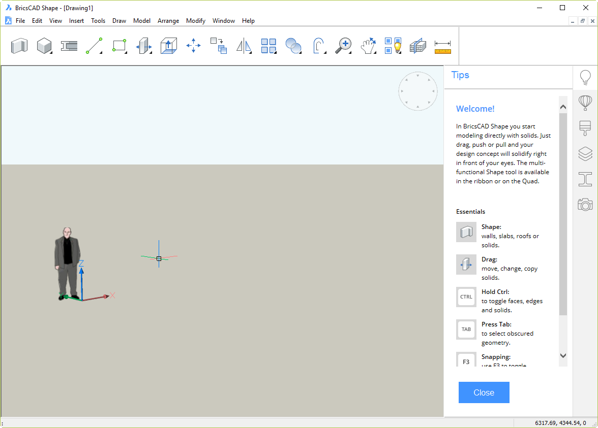
Shape is a 3D direct modeling application. At the core, it’s a simplified BricsCAD BIM. That means it’s small, fast, stable and it uses 2018 DWG as its native format. These are all good things. It’s obviously aimed at the AEC market, but there’s nothing to stop anyone using it for anything. Use it as a lightweight DWG viewer/editor if you like.

As you can see, it has a very simple, clean, cut-down interface. That dude is French Architect Jean Nouvel, by the way. He’s a block; you can erase him. He doesn’t appear in DWG files from other sources you open in Shape.

The idea is to do most of your work with the 18 buttons in this mini-ribbon/monster toolbar thing:

For less common operations, there is a set of pull-down menus. Although it’s hidden by default, you can even turn on a command line (Shift+F2) that will be very familiar to AutoCAD and BricsCAD users. Try to do without it; you will then discover how the excellent Quad Cursor interface (inherited from BricsCAD) uses AI technology to save you time and clicks.

How do I get it?

Click this link, enter your email address (no, they won’t sell it to spammers), and download away. Unlike Autodesk downloads, there are no nasty Akamai download managers to contend with, no multi-stage install processes, no massively bloated files, just a straightforward download of a 212 MB MSI installer. Time to download for me on ADSL2 was 2m 56s. The install time, including user interactions was 36s. Time for the first startup, including online registration, was 15s. That got me to the startup screen. The time for the first drawing startup was another 10s.

You can be using Shape in under 4 minutes. That is, you could be using it yourself in less time than it takes to read what I have to say about it.

How is it licensed? How much is it?

It’s a perpetual license, and it’s free. Bricsys has stated that it will always be free. Not much to complain about there.

So what’s in it for Bricsys?

The problem Bricsys faces in churning over large numbers of Autodesk’s disgruntled customer base is not the products. The products are fine. BricsCAD is notably superior to AutoCAD in a bunch of significant ways (while remaining inferior in a handful of less important ways), and costs a fraction as much.

No, the problem Bricsys faces is in persuading large numbers of people to try its products. Shape is an attempt to make that happen. It’s an ice-breaker in a way that goes beyond the usual 30-day free trial product.

There’s hardly any bar to entry; anybody with an email address can own it with zero investment. The interface has been kept very simple and there are a whole bunch of bite-size tutorial videos that demonstrate how to do things. If this product can create a buzz and get people to use a Bricsys product, half the battle is won. The models it creates are ready to be easily taken to the next stage using the full, paid product, BricsCAD BIM.

It’s not SketchUp
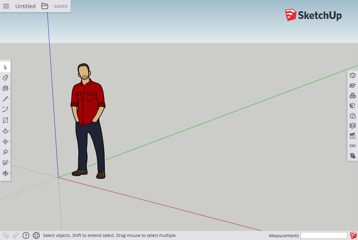
There are superficial similarities between Shape and the discarded-by-Google product, Trimble SketchUp.

However, there are very significant differences. SketchUp Free is a cloud-based product that works inside your browser (the paid product is currently a desktop product). Shape is a standalone application that does not require the Internet. SketchUp has its own file formats; getting those models into CAD or BIM is fraught. Shape is not just using industry-standard DWG file format, it’s a proper, efficient, accurate CAD application. Because it’s a cut-down version of what Bricsys is hoping you will use to fully develop the models later, there is no translation. The model you build in Shape opens directly in BricsCAD BIM where automatic classification of building elements can take place.

BricsCAD Shape. It’s free, it’s easy, it’s DWG, it’s CAD, it’s 3D, and it’s a pathway to BIM. It could change the game. I have no way of predicting whether that will happen. But if it does, it’ll be another kick in the guts for a dormant Autodesk that has largely given up on improving its products.

Autodesk survey for 3D users

Autodesk is conducting a survey about 3D work in AutoCAD. Here is the announcement:

Do you use 3D in your AutoCAD work? We want to learn from you!

If you are familiar with 3D modeling, lighting, rendering, or visual styles, either in AutoCAD or in other software, we’re interested in finding out more about how you work.

We are conducting a survey to learn about your 3D work process. The survey should take less than 10 minutes to complete, and your feedback will help us improve future versions of AutoCAD. Here is the link:

https://www.surveymonkey.com/s/72HDGVG

We are also conducting a series of paid research sessions over the next few weeks. At the end of the survey, you will have a chance to sign up for sessions if you are interested.

Who we’re looking for: People who are familiar with lighting, rendering, or visual styles

What it involves: If you are selected to participate, we will get in touch with you to set up a study time. During the 1-hour session:

* You will work 1-1 with a facilitator using meeting software and the phone
* We will observe part of your work process and ask questions
* You will be given a $30 Amazon gift card as a thank-you for your time

Dates: We are conducting studies during the week of March 7th and the week of March 14th.