Author Archives: Steve Johnson

About Steve Johnson

Steve is the owner of cad nauseam, has been a CAD specialist since 1985. His roles have included CAD management, development, consulting and technical writing. Steve has also been a contributing editor for Cadalyst magazine, President of the Western Australian AutoCAD User Group, and a Vice President of CADLock, Inc. He is also an international veteran fencing champion.

Hexagon acquires Bricsys

The acquisition of Bricsys by Intergraph-acquirer Hexagon AB was just announced at the Bricsys 2018 conference in London. That means that BricsCAD is part of an organisation with 2017 sales of €3,470 million – significantly larger than Autodesk.

This follows on from Hexagon’s previous close relationship with Bricsys that led to its CADWorx series of AutoCAD-based products also being available on the BricsCAD platform.

Hexagon Executive VP Rick Allen took the stage to explain his enthusiasm for the BricsCAD product, noting many of the strong points that will be no news to regular readers of this blog. Interestingly, he was not shy of pointing out the various technical and policy areas where Bricsys is strong and Autodesk is weak. That included the ongoing availability of perpetual licenses.

Erik De Keyser announced that he’s not going anywhere following the Hexagon acquisition, which was greeted with applause.

Interesting days lie ahead for Bricsys now it has a parent that’s more powerful than Autodesk.

A & B Tip 9 – drilling holes 3 – counterbores

In this series of posts, I’ll be providing tips that show how to do something in both AutoCAD and BricsCAD, hence A & B.

The Series

The idea behind this series is to provide useful information for several sorts of reader:

  1. AutoCAD users.
  2. BricsCAD users.
  3. People in the process of transitioning from AutoCAD to BricsCAD and who need to know what to do differently (if anything).
  4. People considering transitioning from AutoCAD to BricsCAD and who want to know about the differences and similarities.

Counterbored holes

This post continues to explain more about how to put holes in your 3D models. In this post I’ll be describing how to construct counterbored holes. Hint: the most efficient method is described last.

I’m going to start with this model and use different methods to create three counterbored diameter 10 holes that go through the block, each with a diameter 20 x 18 deep counterbore. I’ve placed circles of diameter 10 and 20 in place to indicate where the holes are going to go, and in some cases to act as the basis for extrusion.

If you’re unsure about how to locate these circles in exactly the right spots in 3D space, see my earlier drilling holes posts, part 1 and part 2.

Extruding circles

Assuming we have appropriate circles to work with, we can extrude them to create cylinders, then subtract them. This works in basically the same in both AutoCAD and BricsCAD, but there are differences:

AutoCAD BricsCAD
Invoke the EXTRUDE command:
Select the inner circle and press Enter to complete the selection process:
Move your cursor down and click when the extrusion goes beyond the bottom of the block:
Enter a negative number that equals or exceeds 100 (the thickness of the block):
If you just pick a point as per AutoCAD, the extrusion will go up rather than down. It’s also possible to point to the direction and amount to extrude by using the Direction subcommand and picking two points, for example a top and bottom corner of the solid.
Repeat the above process for the second circle, but this time specify an extrusion height of 18 while the cursor is located such that the extrusion is going down rather than up:
Repeat the above process for the second circle, but this time specify an extrusion height of -18. It has to be negative, otherwise the extrusion will go up even if you’re pointing down (unlike AutoCAD).

We’ll subtract these cylinders later.

Drawing cylinders

You can draw cylinders to subtract without needing construction circles. In this case one of the circles is just used to help locate the cylinder center point, but you can use other methods that involve no construction geometry instead, as explained in my first drilling holes post.

AutoCAD BricsCAD
Invoke the CYLINDER command (Solid, not Surface):
Invoke the CYLINDER command (Solids, not Meshes):
Locate the center of the cylinder, in this case using the center object snap:
Locate the center of the cylinder, in this case using the center entity snap:
Enter a radius of 5:
Move your cursor down and click when the extrusion goes beyond the bottom of the block:
Repeat the above process for the second cylinder, but this time specify a height of 18 while the cursor is located such that the extrusion is going down rather than up:
Repeat the above process for the second cylinder, but this time specify a height of -18:

Subtracting the cylinders

We can subtract all four cylinders at once to create two of the counterbored holes. This process is the same in both applications.

AutoCAD BricsCAD
Invoke the SUBTRACT command:
Select the main solid as the object to subtract from and press Enter to complete that selection. Then select the cylinders to remove. This is easiest with an implied window. Pick a corner point containing no objects, starting on the left. Then pick the opposite corner to the right.
Press Enter to complete that selection and the command.
End result:
End result:

Note that the first method replaces the circles with cylinders. The second method only uses the circles to help locate the center; they don’t really need to be there at all and are ignored.

Presspulling or Push/pulling

As described before, planar objects such as circles can be extruded by presspulling them. We’ll use that method to create the third counterbored hole. In this case, the operations differ somewhat between AutoCAD and BricsCAD.

AutoCAD BricsCAD
Hold down Ctrl+Shift+E to turn on dynamic presspull mode, hover over the space between the two circles and pick:
Hover over the inner circle. You should see the Quad Cursor appear, suggesting a push/pull operation. Pick the icon to accept that operation:
Now you can release Ctrl_Shift+E. Move your cursor down and enter 18:
Move your cursor down beyond the bottom of the block and pick.

Note the on-screen reminder that you can hit the Ctrl key to switch between several different types of push/pull operations. We can ignore this because in this case we want to use the default. However, it’s worth noting that this feature exists because it’s very handy.
Hold down Ctrl+Shift+E to turn on dynamic presspull mode, hover over the inside of the inner circle and pick. Release Ctrl+Shift+E, move your cursor down beyond the bottom of the block and pick:
Hover over the outer circle and pick the push/pull icon on the Quad Cursor. You could enter a height of -18, but in this case there’s a handy nearby hole counterbored to the correct depth and we can just pick the center of that instead:
In the AutoCAD presspull end result, the circles are left behind so if you don’t want them you will need to erase them.
Note also that your UCS origin is changed by this operation even if dynamic UCS is turned off. To restore it, use UCS Previous or use the UCS menu under the ViewCube to change it to World or any other named UCS:
In the BricsCAD push/pull end result, the circles are converted to holes so no more action is required. No UCS restoration is necessary.

Summary

Assuming you have construction circles in place, presspulling is the most efficient of the three methods in AutoCAD, even allowing for the tidy-up required at the end.

BricsCAD’s Quad-based push/pull operation is the most efficient method of the lot. Hover, pick, pick and hover, pick, pick is enough to create a counterbored hole.

Next: countersunk holes.

My Real World BricsCAD series is coming soon on the Bricsys blog

In February, my first Bricsys blog post appeared:

Inside Bricsys: Interviewing the creator of BLADE – the new Visual LISP IDE in BricsCAD V18.2

This was an amalgamation of my two similarly named posts on this blog where I interviewed BricsCAD’s Torsten Moses about BLADE, the LISP IDE that arrived with BricsCAD V18.2.

Today marked my first original-material post on the Bricsys blog:

Real World BricsCAD Series Coming Soon

I encourage you to hop over to the Bricsys blog to check it out. I’ve been interviewing real people about their use of BricsCAD and will be reporting what they have to say.

Disclosure: Bricsys is paying me to interview these people and produce these pieces.

Bricsys is not, however, paying me to sugar-coat anything. I’m being left alone to interview who I like and write it up as I see fit. A quote from today’s post will give you some idea of what’s in store:

The posts in this series aren’t going to be your average corporate-waffle puff-pieces. I mean, who reads those things anyway?

If you have used BricsCAD and are willing to be featured in this series, I would love to hear from you. Please contact me using this form and I will be in touch. In addition to the interviews in the pipeline, I have already had my first response to this invitation. A site in Austria with 70 users and lots of custom programming sounds like something I can get my teeth into.

Video – Steve on BricsCAD Unplugged

Following on from Lynn Allen and Robert Green’s guest appearances on the BricsCAD Unplugged webcast a couple of weeks ago, this time it was my turn.

Last night (my time) I was the special guest on the episode BricsCAD Unplugged – Steve Johnson 5 surprises moving to BricsCAD. I’m introduced at 2:12 and appear at 3:30. Here’s the full video:

In this week’s episode, you’ll witness:

  • Me discussing the five biggest things that pleasantly surprised me about BricsCAD. (I have more than five, but time was limited).
  • Don Strimbu bribing me with drinks containers.
  • An actual printed copy of Cadalyst magazine from 1995, complete with my old column Bug Watch (1995-2008).
  • The excellent euphemism, “You’re generally pretty conservative in terms of your praise.”
  • Don throwing me a curveball by introducing my points out of order!
  • The announcement that I’ll be at Bricsys 2018 in London and possibly participating in the BLADE session.
  • Me saying, “No. I’m wrong.”
  • Me drinking a glass of wine (parental guidance advised – alcohol consumption depicted). If you care, it’s a Shiraz (that’s Syrah if you’re American) from South Australia’s Limestone Coast region.
  • Total lack of coordination from everyone in raising our drinks at the end.

Thank you to the Bricsys crew for the invitation, it was a blast! If you ever want me on again, I’ll be happy to oblige.

For future reference, these live broadcasts run on the Bricsys Facebook page and are then quickly transferred to YouTube.

Autodesk Fusion 360 massive subscription price rise/drop

Autodesk’s cloud-based 3D design tool, Fusion 360, is changing price and structure from 7 October 2018. Whether it’s a huge price rise or a huge price drop depends on your perspective.

Price rise

The current annual subscription cost for Fusion 360 is US$310 and that’s going to change to US$495, which represents a 60% price increase. Existing subscribers are being kept at the same annual rate of US$310 or US$300 (depending on when you first subscribed) “for as long as you renew”. Existing subscribers, that looks like a promise to never increase your prices as long as you keep up the payments. Make sure you capture and retain all of Autodesk’s statements on this matter, in case that promise eventually gets forgotten.

However, for that amount you’ll now be getting the same features that are currently in Fusion 360 Ultimate; the lesser and greater versions are being amalgamated and just called Fusion 360.

Price drop

The current annual subscription cost for Fusion 360 Ultimate is US$1535. As that’s going to change to US$495, that represents a 68% price drop.

Is it fair?

If you currently use Fusion 360, even if you have no use for Advanced Simulation, Advanced Manufacturing or Generative Design, it’s not bad news. The only downside is that you’ll now be paying more if you need to add seats, or if you temporarily drop and resume subscription.

If you currently use Fusion 360 Ultimate, you are probably going to be overjoyed at spending a lot less in future. If you just paid US$3,070.00 for a 2-year subscription that’s about to be worth US$990, you might be less pleased. To assuage your ire, Autodesk will be giving you (and all existing annual subscribers) another 24 months subscription, gratis. Still, depending on the term length and renewal timing, some customers are going to be much luckier than others. That might annoy the less fortunate.

I think Autodesk has been very fair and reasonable with the way it has handled these changes. However, it does serve as a reminder that once you’re a subscriber, you’re at the mercy of your software company.

Mac users rejoice – at long last, a LISP IDE comes to OS X

CAD’s best LISP development environment has come to the best “AutoCAD for Mac”. It should come as no surprise to anyone that this has occurred without Autodesk’s involvement.

What’s happened?

With the release of BricsCAD (Mac) V18.2 (currently V18.2.23-1 to be precise), BLADE (BricsCAD’s much-superior equivalent to VLIDE) has been added to BricsCAD

See here for the release notes and here to download. Make sure you select the Mac version:

Significance

This is pretty significant for anybody serious about using DWG-based CAD on the Mac. AutoCAD without LISP is hardly worthy of the name, which is why I’ve never been keen on AutoCAD LT from the moment LISP was yanked out of it just before release in the early 90s. There has never been an integrated development environment for AutoCAD for Mac (either in the first iteration in the 1990s or the second attempt in the 2010s) and I think I can safely predict that there’s never going to be one. I expect AutoCAD for Mac’s LISP to remain forever in 1990 mode.

Compatibility

One problem a small number of users may face when developing for Mac with BLADE is that of downward compatibility. In case you’re wondering, BricsCAD (Mac) to AutoCAD for Mac is very much a downward direction, particularly in the area of LISP. The LISP in AutoCAD for Mac is famously half-baked with large portions of functionality missing, including no ability to control dialog boxes. BricsCAD (Mac)’s LISP is very much more capable, so while compatibility between AutoCAD for Windows and BricsCAD (Mac) is strong, you can’t say the same for LISP compatibility between AutoCAD for Windows and AutoCAD for Mac.

Half of the stuff you write for AutoCAD in Windows is just going to fail when you try to run it in AutoCAD for Mac. Much more of it is going to work in BricsCAD (Mac). While you can now write, debug and run your LISP code efficiently in BricsCAD (Mac) and it’s practically guaranteed to run just fine in AutoCAD and BricsCAD for Windows, it will be very easy to write stuff in BricsCAD (Mac) that doesn’t work in AutoCAD for Mac. Of course, the same downward compatibility problem applies to writing stuff in AutoCAD for Windows using VLIDE.

If you’ve moved on completely from AutoCAD for Mac to BricsCAD (Mac), that’s not going to be a problem. Bircsys building a notably better product that’s significantly more compatible with the main game is not something anybody could reasonably condemn. However, but it’s something to bear in mind if you are hoping to write code that runs on both AutoCAD and BricsCAD for Mac.

Summary

That caveat aside, it’s all good news for Mac CAD users. You already had a product available that would run a much higher percentage of the huge library of LISP out there than AutoCAD for Mac would. For the first time in history, you now also have access to a professional LISP development tool. Lucky for you, it’s the best such tool on the market.

Explaining the four tiers of AutoCAD license

Yesterday’s tiers

Once upon a time, long long ago, you could buy AutoCAD with or without sets of features  called Advanced Drafting Extensions (ADE) containing optional extras such as dimensioning. At one stage you could buy four tiers of AutoCAD license at different prices:

  1. AutoCAD
  2. AutoCAD + ADE1
  3. AutoCAD + ADE2 (incorporating ADE1)
  4. AutoCAD + ADE3 (incorporating ADE1 and ADE2)

(Interestingly, the above situation is similar to the current arrangement with BricsCAD, where BricsCAD Classic, Pro and Platinum are available with incrementing prices and feature sets, with BricsCAD BIM and Sheet Metal available on top of Platinum).

As almost everybody bought AutoCAD + ADE3 anyway, the ADEs were eventually absorbed into the main product and AutoCAD became just AutoCAD again. Later, the AutoCAD line would split again into AutoCAD LT, AutoCAD, and various AutoCAD-based vertical products such as AutoCAD Mechanical and Civil 3D.

Today’s tiers

Fast forward thirty-odd years and AutoCAD licenses are again available in four tiers (even if we ignore AutoCAD LT and Civil 3D). For an AutoCAD 2019 user, these are:

  1. A perpetual license holder who allowed maintenance to lapse after activating AutoCAD 2019.
  2. A perpetual license holder still under maintenance.
  3. A subscription user who switched from maintenance under the Move to Subscription offer prior to the release of AutoCAD 2019.
  4. A subscription user who switched from maintenance under the Move to Subscription offer after the release of AutoCAD 2019 or who started a new full-price subscription at any time.

Note that Tier 1, etc. is my description of the category and not Autodesk’s.

What the tiers mean

This table shows what is available to customers in each of the above tiers:

Tier Perpetual Usage Updates Support Cloud Shared Views Web/Mobile Toolsets
1
2
3
4

Here’s what the table headings mean:

  • Perpetual – a perpetual license that allows continued use into the future without requiring further payment.
  • Usage – rights to use the license at home, use of previous versions and internationally.
  • Updates – formerly known as Service Packs, these bug fixes and minor feature enhancements are withheld from customers who are not actively paying Autodesk.
  • Support – the ability to log a service request that will be addressed by a technician. There are actually multiple levels depending on how much you pay: Basic, Advanced and, for subscription users, the ability to schedule a call to talk to somebody.
  • Cloud – online services such as storage and rendering.
  • Shared Views – formerly available to all AutoCAD 2017 and 2018 users, this feature was renamed, updated and made subscription-only in AutoCAD 2019.
  • Web/Mobile – the AutoCAD Web and AutoCAD Mobile App viewer/markup tools.
  • Toolsets – the ‘Only One AutoCAD’ set of AutoCAD-based verticals now called Specialized Toolsets (excluding Civil 3D). Note that if you’re a customer in Tier 3 who originally had a vertical product (e.g. AutoCAD Mechanical), you will still have access to that toolset and plain AutoCAD, but not the others.

Moving to three tiers

Felice at Autodesk has explained that Autodesk plans to move everybody in Tier 3 to Tier 4 at some point in the future (subject to legal disclaimers). But for now, if you took up the Move to Subscription offer at the wrong time, you don’t yet have access to Specialized Toolsets.

Thanks are due to Felice for patiently answering my questions to clarify the situation and explain the detail.

Where on Earth is Lynn Allen going?

Well, this is a fun video for CAD geeks. The third in the BricsCAD Unplugged series of weekly webcasts, this one promotes the Bricsys 2018 conference which will be held on 23 and 24 October in London.

These live broadcasts run on the Bricsys Facebook page and are then quickly transferred to YouTube.

This one is interesting because of the people in it and some interesting news. It features Bricsys regulars Don Strimbu, Heidi Hewett, Vince Aman and Matt Olding, but also a couple of special guests. First on the scene is Robert Green (see 4:57) but the real surprise comes at 9:23 when somebody who may be familiar to you appeared in the bottom right corner:

The fun part comes when Lynn is “persuaded” with the promise of beer to turn up in London. Lynn won’t be going to AU this year (“My invitation must have got lost in the mail!”), along with quite a few others. So if you’re going to Vegas you’ll have to put up with somebody slightly less popular on stage instead.

So Bricsys 2018 in London is where all the cool people will be. Lynn and Heidi will be there and Robert will be rocking out with the Bricsys band. I might not be lead-guitarist-cool but I’ll be there too. What is said in the video about Bricsys conferences being great for meeting people is very true. Everybody’s approachable, right up to Bricsys CEO Erik De Keyser, so come up and say hello.

If you want to join us, sign up here. At the time of writing, there are just a few hours until the end of Early Bird pricing on the tickets.

Did I mention it’s being held in a brewery?

Oh, and there’s some CAD stuff.*

Here’s the full video:

* The CAD stuff alone made the Bricsys Conferences well worth attending for me in past years.

A & B Tip 8 – drilling holes 2

In this series of posts, I’ll be providing tips that show how to do something in both AutoCAD and BricsCAD, hence A & B.

The Series

The idea behind this series is to provide useful information for several sorts of reader:

  1. AutoCAD users.
  2. BricsCAD users.
  3. People in the process of transitioning from AutoCAD to BricsCAD and who need to know what to do differently (if anything).
  4. People considering transitioning from AutoCAD to BricsCAD and who want to know about the differences and similarities.

Drilling holes

This post continues to explain more about how to put holes in your 3D models. More than one method involves starting with a planar object (e.g. a circle for a cylindrical hole), but it needs to be in the right spot and in the right plane. The most efficient way of drawing an object in a given plane, where that plane exists on a 3D solid, is to use Dynamic UCS.

Dynamic UCS

First, we need to make sure Dynamic UCS is turned on. In AutoCAD, the Dynamic UCS icon looks like this:

If that’s not visible, you may need to make it visible using the hamburger menu on the far right of the status bar:

In BricsCAD, the text-based toggle (like the one AutoCAD users have been asking to return ever since it was removed a few releases ago) is DUCS:

Just in case that toggle’s not visible, there’s a list of toggles in a menu at the bottom right of the BricsCAD user interface, too:

You can also toggle the Dynamic UCS status in both applications using F6.

Having established that DUCS is on, invoke the Circle command. Hover over the plane that’s on the left as we’re looking at it, thus:

You are now working in a temporary UCS with an origin point in one corner of the 3D solid’s face, and as you move around you can use the coordinate display to get an idea of where the coordinates lie. If I enter -100,50 this is used in relation to the origin of the dynamic UCS and I will get a circle here:

Things work in a similar way in BricsCAD. You don’t get the on-screen dynamic coordinates, but you can still see them in the status bar and you do get a UCS icon that shows you how the temporary UCS is aligned. If you move your cursor around, you will be able to obtain different UCS alignments and easily see where the origin is and which way X and Y are oriented:

With this visual information and the dynamic UCS shown above, you can enter 100,50 to place the circle in the same spot as in AutoCAD.

Now we have our circle (and it could just as easily be a filleted rectangle or any other shape), we could extrude it as described in my previous post. Instead, let’s push and pull it into shape as described below.

Presspulling or Push/pulling

Instead of using the EXTRUDE command, planar objects can be extruded by presspulling them. Before drilling some holes, I should explain that there are several differences (some subtle) between extrusion and presspull:

  • Extruding replaces the original objects whereas presspulling leaves them in place and creates new objects.
  • The EXTRUDE command expects you to select objects to extrude; the PRESSPULL command allows you to point within an enclosed area. Depending on what you’re starting with, one command will be more suitable than the other.
  • Extruding an area enclosed by individual objects (e.g. lines) extrudes the objects into planar surfaces. Presspulling such an enclosed area results in a 3D solid being created based on an extrusion of the enclosed area.
  • An EXTRUDE of an enclosed planar object (e.g. circle, closed polyline) creates a 3D object. PRESSPULL can also do this, but when the planar object lies on the surface of a 3D solid, it can also create a hole in that solid.
  • Both commands can be used on faces of 3D solids; EXTRUDE will create a new solid based on an extrusion of that face and PRESSPULL will modify the original solid.

Presspulling in AutoCAD

In AutoCAD, you can use the PRESSPULL command:

Alternatively, you can use Ctrl+Shift+E to invoke presspulling: hold all three keys down and point within an enclosed area. Here’s an example. A circle has been drawn on the left vertical surface of our solid. Hold down Ctrl+Shift+E together and pick the interior of the circle. Let go of the keys and move your mouse to the right:

Pick a point beyond the extents of the solid. A hole is automatically created in the solid without having to explicitly subtract it, thus:

User actions required: a three-key combination and two picks. Note that the original circle is still present and if you don’t want it there you will need to erase it.

Push/Pulling in BricsCAD

In BricsCAD, there is no PRESSPULL command. Instead, the closest equivalent command name is DMPUSHPULL (the DM stands for Direct Modeling).

This command expects to work on faces of 3D solids, which is not exactly what we’re after for drilling holes. Instead, we use the DMEXTRUDE command. Now it might seem confusing that there are different commands to use for similar things, but in practice that doesn’t matter. That’s because we can just use the Quad Cursor and really not care what the underlying command is called. If you hover over a 3D solid’s face, the Quad Cursor gives you the options you need for dealing with that, and if you hover over a circle you are given the appropriate options for that instead.

Here’s the same example as above, this time done in BricsCAD. Hover over an object that defines an enclosed area, in this case our circle:

The Quad Cursor uses AI technology to initially provide the option that it thinks you’re most likely to use with that object under the current circumstances. I find it’s remarkably good at guessing what you want to do. If it’s wrong, you can get at a whole bunch of other options with a bit more hovering, but in this case it’s right; we do want to extrude the circle. Pick that icon, move over to the right and pick. That will create the hole:

User actions required: a hover and two picks. Again, the original circle remains behind and will need to be erased if you don’t want it left hanging around.

What about more complex holes? There are more tips and tricks coming, so watch this space.

A & B Tip 7 – drilling holes 1

In this series of posts, I’ll be providing tips that show how to do something in both AutoCAD and BricsCAD, hence A & B.

The Series

The idea behind this series is to provide useful information for several sorts of reader:

  1. AutoCAD users.
  2. BricsCAD users.
  3. People in the process of transitioning from AutoCAD to BricsCAD and who need to know what to do differently (if anything).
  4. People considering transitioning from AutoCAD to BricsCAD and who want to know about the differences and similarities.

Drilling holes

This post explains how to put holes in your 3D models. This post will cover some fairly straightforward topics but I intend to cover more involved details in future posts. I’ll assume you have a basic understanding of creating 3D primitives and the boolean operations (union, subtract and intersect). I will be using the 3D Modeling workspace in both AutoCAD and BricsCAD. I’m going to start with the dynamic UCS feature turned off and the 2D Wireframe visual style.

Vertical cylinder subtraction

Let’s take the simplest case. You have a solid and you just want to place a cylindrical hole in a known location that you already have geometry you can snap to. For example, you want to drill a DIA 40 hole right through this part, using the centerlines shown:

Start with the CYLINDER command:

AutoCAD BricsCAD

Pick the intersection of the two centerlines, enter a radius of 20 and a height of 100. You don’t have to be precise with the height, you can just point to any height that’s over 100:

To create the hole, use the SUBTRACT command:

AutoCAD BricsCAD

With this command it’s important to select the objects in the right order. Select the object(s) you’re substantiating from first, then press Enter to finish the selection process for those objects. Then select the object(s) you’re subtracting and press Enter to finish that selection process. That will give you your hole (temporarily switched to X-Ray visual style for clarity):

Extruding a circle

Instead of creating the cylinder diectly, you can instead extract a circle. This is an extra step if you don’t already have a circle of the right size in the right place, but less work if you do. For example, if you’re converting a 2D drawing to a 3D model, you’ll probably have the circle already.

Invoke the EXTRUDE command:

AutoCAD BricsCAD

Select the circle, press Enter to finish the selection (because you can extrude several objects at once) and specify a height of at least 100, as with the CYLINDER command. Subtract the resultant cylinder and you’re done.

It’s important to note that extrusions work perpendicular to the plane of the object(s) being extruded. In this case the cylinder is created vertically because the circle lies flat (in terms of the World Coordinate System). If you have a circle lying in a different plane, the extrusion will be perpendicular to that plane. For example, here a circle that lies in a vertical plane is being extruded horizontally:

Drawing a circle in the other planes

That’s all well and good if you have a circle in the right plane, but what if you need to draw one? You have several alternatives.

One method is to draw your circle in whatever plane you like, then use the ALIGN command to move it into place. That works, but it’s not that efficient.

Alternatively, you can change your UCS to align with your desired plane, and then just draw your circle. That can be fiddly, but if you have a handy solid object containing the plane you want to draw in, you can use the UCS command’s OBject option (hot tip: E for Entity does the same thing). By carefully hovering over the plane, you can set up your desired UCS with one click and a lot less tiresome fiddling around than trying to work out what the other (somewhat arcane) options of the UCS command all mean. Here, the UCS command’s OBject option is shown in action:

Note that this is an example of one of the very few things that works in AutoCAD but not BricsCAD. The UCS command’s OBject (and Entity) option exists, but you can’t use it to align a UCS with a solid’s face. You can, however, use the UCS command’s Face option. That exists in both applications, but I prefer the way it works in BricsCAD where the origin of the UCS is placed in one corner of the face with no further interaction required. In AutoCAD, the default is to place the UCS origin at some random point you used to select the face so if you need to locate points precisely there is a bit more messing around required.

Upshot: Use UCS E in AutoCAD and UCS F in BricsCAD.

In any case, there are other, more efficient ways to skin this particular cat. In my view, the most efficient way of drawing an object in a given plane, where that plane exists on a 3D solid, is to use Dynamic UCS. I’ll explain that, and how to push and pull your holes into submission, in the next post.

Fix released for Autodesk subscription licensing error (yes, another one)

Providing yet another entry in the it’ll never happen again file, Autodesk has issued a fix for an AutoCAD 2018 subscription licensing crash.

Thankfully, it’s not compulsory to use the execrable Autodesk desktop app or malware-like Akamai download manager to obtain this fix. There are direct links for the 32-bit and 64-bit fixes.

Lessons we learned from this:

  • AutoCAD doesn’t just phone home once every 30 days to maintain even a long-term a subscription license, it phones home 24 hours later too. And probably every 24 hours after that.
  • Desktop software that relies on the internet to continue working is a terrible idea.
  • Yes, it will happen again.

Autodesk subscription price rise certainty

In my previous posts exploring the costs associated with various CAD software licensing scenarios, there was always a need for assumptions because Autodesk had failed to provide any pricing information beyond a point a year or so from now. As a result, expecting the worst appeared to be the safest strategy.

To Autodesk’s credit, this situation is now partially addressed. From this Autodesk web page:

We’re extending our price commitment through 2028 for customers who continue to renew after they switch. The special Move to Subscription renewal suggested retail price will increase by no more than 5% in 2021, 2023, 2025, and 2027. There will be no change to the renewal suggested retail price in 2022, 2024, 2026 and 2028.

There are some weasel words in the fine print that allow Autodesk some wriggle room, but let’s go with the numbers we have. It works out to an increase of 21.5% by 2027. If you’ve already switched and you’re paying $1000 a year then you’ll be paying $1215 a year in 2027 and 2028. That’s a pretty reasonable level of increase. Of course, the total number of dollars you’ll hand over is several times higher than for, say, keeping a permanent license of BricsCAD up to date.

The above refers to customers who give up their perpetual licenses that are currently under maintenance and switch to subscription (rental) under the special conditions of the Move to Subscription offer. Pricing is still in the air for you millions of stubborn users who insist on owning your software licenses, and for those who are paying sky-high rates under the conventional subscription deal.

There are also no guarantees about what you’ll be paying for. If AutoCAD 2019‘s anything to go by, you can expect little improvement, feature removal and poorer performance.

A & B Tip 6 – making polylines when you don’t have any

In this series of posts, I’ll be providing tips that show how to do something in both AutoCAD and BricsCAD, hence A & B.

The Series

The idea behind this series is to provide useful information for several sorts of reader:

  1. AutoCAD users.
  2. BricsCAD users.
  3. People in the process of transitioning from AutoCAD to BricsCAD and who need to know what to do differently (if anything).
  4. People considering transitioning from AutoCAD to BricsCAD and who want to know about the differences and similarities.

Why might you need a polyline?

In my last post (A & B Tip 5 – polyline areas) I described different methods of finding the areas (and perimeters) enclosed by polylines. That’s all well and good, but what if the objects that enclose your area aren’t nice convenient polylines? This post will help you make some. There are other reasons you might want polylines rather than whatever you have now. These include:

  • You can offset a polyline in one go rather than offsetting multiple objects and then joining them together.
  • You can apply fillets to a whole polyline with a single pick rather than lots of them.
  • A polyline can be extruded to make a 3D solid (or hole).
  • You can use a polyline to define a path that is used to extrude or sweep another polyline to make a solid with automatically mitred corners.
  • You can apply a width to a polyline and override that width for individual segments.
  • You can use a polyline as the basis to create a region, which allows you to do various cool things such as perform boolean operations on 2D objects.
  • Using polylines to define a hatch boundary can be less error-prone than using individual objects.
  • You can locate the geometric center of a polyline with the GCE object snap.
  • A polyline’s linetype can be persuaded to flow around the whole polyline rather than being confined to individual segments. In some cases, this means you will see a linetype where you would otherwise see only solid lines.

Having established various uses for polylines, and assuming you already have some objects and don’t want the tedious job of drawing over them manually, what can you do? Read on.

Note: in this post, the operations are exactly the same in both AutoCAD and BricsCAD with a couple of minor exceptions that I will point out as I go along.

PEDIT Join

If you’re fortunate enough to have a series of lines, polylines and/or arcs that are connected end-to-end without overlap to exactly define the area you want, then you can use the PEDIT command’s Join option to convert those objects to a single polyline. The command sequence dates from the mid-80s and is rather convoluted:

Command: PEDIT
Select polyline or [Multiple]: [pick an object]
Object selected is not a polyline
Do you want to turn it into one? [Enter] (this only appears if you pick a line or arc)
Enter an option [Close/Join/Width/Edit vertex/Fit/Spline/Decurve/Ltype gen/Reverse/Undo]: J
Select objects: [select a bunch of objects]
Select objects: [Enter]
X segments added to polyline
Enter an option [Close/Join/Width/Edit vertex/Fit/Spline/Decurve/Ltype gen/Reverse/Undo]: [Enter]

Note that the Do you want to turn it into one? prompt can be suppresses if you set PEDITACCEPT to 1. It’s also worth noting that if the properties of the objects vary, then the properties of the first-selected object will be used for the resultant polyline.

If you do a lot of this kind of operation, then it can be made more efficient using a menu macro. Some of us even made commands in LISP to simplify matters. A few releases ago, Autodesk did that for us when it added the JOIN command. BricsCAD followed suit to maintain command compatibility. This command joins various things in various ways, and one of those ways involves creating a polyline.

JOIN

The JOIN command, when applied to the same kind of convenient end-to-end objects described above, performs the same task as PEDIT Join, but with fewer prompts. Why not use it all the time then? Because sometimes it doesn’t work (in AutoCAD, at least). See the video for an example.

Video – PEDIT Join and JOIN in AutoCAD and BricsCAD

BOUNDARY

The BOUNDARY command, unlike the joining commands above, does not require that the objects lie conveniently end-to-end. Any group of objects that form an enclosed area can be used to create a closed polyline. Also unlike the joining commands, the existing objects are not converted to a polyline. Instead, a new polyline is created on top of the existing objects. The current properties (layer, etc.) are used to create the new polyline.

Assuming you’ve set your current properties to match the objects you want to create, invoke the BOUNDARY command (short form BO). A dialog will appear. There are minor differences between the AutoCAD and BricsCAD dialogs, but nothing that need concern us here.

Just pick the button at top left and start picking inside bounded areas. When you’re finished, press Enter and you’ll be left with a bunch of closed polylines. This video shows how it’s done.

Video – BOUNDARY in AutoCAD and BricsCAD


Finally, you can cut out the dialog box altogether and go straight to picking points if you use the command-line version, -BOUNDARY (note the leading hyphen). Just enter -BO, pick pick pick, Enter and you’re done.

A & B Tip 5 – polyline areas

In this series of posts, I’ll be providing tips that show how to do something in both AutoCAD and BricsCAD, hence A & B.

The Series

The idea behind this series is to provide useful information for several sorts of reader:

  1. AutoCAD users.
  2. BricsCAD users.
  3. People in the process of transitioning from AutoCAD to BricsCAD and who need to know what to do differently (if anything).
  4. People considering transitioning from AutoCAD to BricsCAD and who want to know about the differences and similarities.

What area is that polyline?

There are several ways of determining the area enclosed by a polyline. This post goes through the various methods. You will also notice that in each of the methods, you get the length (perimeter) as a bonus.

Spoiler alert: the most efficient methods are at the bottom. There’s a one-click method in AutoCAD (it needs a little setting up first) and a zero-click method in BricsCAD.

LIST command in AutoCAD

The oldest method is the good old LIST command. Although this has been around for ever, here’s how it works in recent AutoCAD releases. Issue the LIST command, select the polyline, press Enter to finish the selection, and above your floating command line AutoCAD will show something like this:

If this display goes away and you want to see it again, hit F2 and it will return. If you have a docked command line, AutoCAD will display the information on the text screen, which it will then display:

If you have a floating command line but want to see the text screen rather than the over-the-command-line popup, you can switch to it using Ctrl+F2.

LIST command in BricsCAD

The command works in just the same way in BricsCAD as it does in AutoCAD with the docked command line.. The main differences are that the BricsCAD default interface has a docked command line, and that the text screen (called Prompt History in BricsCAD) is displayed even when using a floating command line.

If the text screen goes away or is obscured, you can restore it using the familiar-to-AutoCAD-oldtimers keystroke of F2 (not Ctrl+F2, which toggles the ribbon in BricsCAD).

Unit precision in BricsCAD

Another difference you might notice is that the only whole units are displayed. This is because BricsCAD respects the setting of DIMZIN when displaying values in the AREA command and AutoCAD doesn’t. In this drawing, DIMZIN is set to 8, which suppresses trailing zeroes. Because the area is exactly 448.0, BricsCAD displays it as 448. If DIMZIN is not set to suppress trailing zeroes, this doesn’t happen. If DIMZIN is set to 0, BricsCAD displays the area using the setting for linear units precision, LUPREC. If this is 4, the LIST command will display the area as 448.0000, as it does in AutoCAD.

This respect for DIMZIN applies in other places in BricsCAD too. For the remainder of this post I’ll have DIMZIN set to 0.

AREA command in AutoCAD

Another good old method is the AREA command. Issue the command, use the Object option and pick your polyline. You will be shown the area in two places as shown here:

AREA command in BricsCAD

The AREA command works similarly in BricsCAD. Although the options displayed indicate that the subcommand is Entity rather than Object, you can in fact use either E or O to initiate selection of an object. Unlike AutoCAD, the area is displayed in one place only, the command prompt area:

Note that the AREA command in both applications gives you more options, including adding together several areas.

Properties palette in AutoCAD

If you have the Properties palette visible (Ctrl+1 will toggle it on), you can simply select the polyline and the area will be displayed in the palette, thus:

Note that unlike the AutoCAD AREA command, the Properties palette does respect the value of DIMZIN. To display the trailing zeroes, first set DIMZIN to 0.

Properties palette in BricsAD

Using the Properties palette in BricsCAD is identical to AutoCAD. Here’s the display:

Quick Properties in AutoCAD

Quick Properties is a cursor-based cut-down version of the Properties palette. It’s not what you get when hovering, which is this:

What you want is Quick Properties, which you only get when you select an object, for example:

Unfortunately, Area is missing. It was there once upon a time, but there were performance problems so it was removed by default. However, you can add it back in. Invoke CUI and pick Quick Properties on the left. Scroll down on the right and pick Polyline.

Turn on Area (and Length if you want). Pick OK. Now see what happens when you select a polyline:

Note: in AutoCAD 2014 (and maybe others), the Area option was missing. There’s a workaround, but it’s a complex hack and well beyond the scope of this post.

Quad cursor in BricsCAD

The easiest way to find a polyline area in BricsCAD is just to hover over it. The Quad cursor will appear, giving you the information you need:

Alternatives

If you’re doing this regularly, it makes sense to automate it as much as possible. Depending what you want, menu macros might help. There are also various free LISP routines around that do this sort of thing, for example these by Lee Mac. If you have more specific requirements (e.g. automatic area label, export to CSV), then that’s the sort of thing I do for a living so feel free to get in touch.

A & B Tip 4 – turning on toolbars

In this series of posts, I’ll be providing tips that show how to do something in both AutoCAD and BricsCAD, hence A & B.

The Series

The idea behind this series is to provide useful information for several sorts of reader:

  1. AutoCAD users.
  2. BricsCAD users.
  3. People in the process of transitioning from AutoCAD to BricsCAD and who need to know what to do differently (if anything).
  4. People considering transitioning from AutoCAD to BricsCAD and who want to know about the differences and similarities.

Your First Toolbar

If you are using a ribbon-based workspace, you may want to have some toolbars visible, too. There are several reasons you might want to do this. You might want some buttons to be consistently visible, no matter what the ribbon state. Although the QAT in AutoCAD provides some toolbar space, you might want more space than it offers. You might also want toolbar controls that are not available in the QAT; several of them only work in conventional toolbars. You might want the buttons in a different place, such as down one side or on a second screen.

If you have at least one toolbar visible already, things are easy. If you right-click on that toolbar, you will get a menu that allows you to turn on any other toolbar in the same customization group (CUI or CUIx file). Here it is in AutoCAD:

Here’s the equivalent in BricsCAD:

Note that in BricsCAD, the list of toolbars is one level down because the first-level right-click menu in BricsCAD gives you many more interface options.

What if the toolbar you want to turn on is in a different customization group? You can get at those easily enough by right-clicking on any blank (unused) area of a docked toolbar area. AutoCAD:

You can do the same in BricsCAD:

The difference with BricsCAD is that you don’t need to have a docked toolbar with spare space in it to access toolbars in different groups. They’re all available by right-clicking any toolbar button, docked or not.

That’s all easy enough, but what if you don’t have any toolbars visible? You’re stuck in a Catch-22 situation. You need a toolbar to click on to load a toolbar. How do you get that first toolbar loaded?

AutoCAD Interactive Method 1

The first trap to avoid in AutoCAD is using the TOOLBAR command. From Release 13 to AutoCAD 2005, that was useful. With the introduction of CUI files in 2006, the TOOLBAR command became a near-useless cut-down version of the CUI command.

Ignore that. If you’re going to use the CUI interface, use the whole thing. Enter the CUI command. In the top left pane, pick the workspace you want to change:

In the top right pane, pick Customize Workspace. In the left pane, expand the Toolbars part of the tree and turn on one of the toolbars:

Pick Done (top right) and OK (bottom). Your chosen toolbar will appear.

AutoCAD Interactive Method 2

If you have your pull-down menu bar turned on, you can get at the toolbars using the Tools menu as shown here:

You can turn on your pull-down menu bar by setting MENUBAR to 1.

Thanks to James Maeding for pointing that out.

BricsCAD Interactive Method

In BricsCAD, you can turn on toolbars interactively even if there are none visible, without having to deal with the CUI interface. Just right-click in any part of the ribbon, and you will see the same menu you get when right-clicking a toolbar area. That gives you access to all of the toolbars in all of the groups.

AutoCAD Command Line Method

If you want to use the command line to turn on a toolbar, you need to use the -TOOLBAR command (note the leading hyphen). You also need to know the name of the customization group and what the toolbar itself. One example is the Object_Snap toolbar within the ACAD group. The command line required is therefore:

-TOOLBAR ACAD.Object_Snap Show

To be sure this will work in all environments, I recommend you add the special characters _ and . thus:

_.-TOOLBAR ACAD.Object_Snap _Show

BricsCAD Command Line Method

In BricsCAD, you don’t need the leading hyphen in the TOOLBAR command (although you can use it if you like). The customization group and toolbar names will be different, but the syntax is the same. For example:

TOOLBAR BRICSCAD.TB_EntitySnaps Show

The recommended special characters also do the same job in BricsCAD:

_.-TOOLBAR BRICSCAD.TB_EntitySnaps _Show

What’s new in AutoCAD 2019 for maintenance customers?

So you’re a long-term customer who has used AutoCAD since it ran on an abacus. You paid for upgrades when you could and switched to maintenance (then called Subscription) when that became the only cost-effective option for keeping current. You’re not about to fall for the subscription (rental) trick; they can prise your perpetual license from your cold, dead fingers.

It’s no secret that the value for your maintenance dollar has been poor for years. Autodesk is jacking up maintenance prices in leaps and bounds; is the maintenance being performed at a rate that matches the amount being charged?

In short, is AutoCAD 2019 enough of an advance over its predecessor to make it worth the maintenance money you paid in advance for it? This post seeks to answer that question.

What you’re not getting

As a maintenance customer, you’re being denied the big item that would make the answer to that question a definite ‘yes’ – Specialized Toolsets. Despite the name and the There Can Be Only One hype, if you’re a renter you’re not getting one AutoCAD that has the extra bits available. You’re getting the availability of a bunch of seven different AutoCAD variants and one add-on (Raster Design), each of which needs to be downloaded, installed and run individually. This initiative has been unkindly referred to as ‘shovelware’, and it’s highly likely that throwing in all of these verticals for ‘free’ means that we’ve seen the end of their meaningful lives. Expect no significant future enhancements and you may avoid disappointment. However you look at it, it’s subscription-only and therefore need not concern us further.

Similarly, as a maintenance customer you’re not getting AutoCAD Web and Mobile. Despite the names, these aren’t AutoCAD. They’re simple online viewing tools with some editing and markup functionality.

What you’re getting taken away from you

You may recall me describing (and praising) the AutoCAD 2017 feature, Share Design View. This was slightly improved in AutoCAD 2018. In AutoCAD 2019 it has been revised again and renamed to Shared Views. Presumably, the Views you’re Sharing are no longer of Designs. Whatever the reason for the rename, it has a sinister connotation. Share Design View is considered obsolete and has been removed. Shared Views has been provided only to subscription customers. The upshot is that this is a feature removal. Yes, you’re getting negative value for your maintenance dollars. This is one of the more petty, vindictive attempts to convince you to go rental. Whoever put their hand up at the product meeting to suggest this particular piece of anti-customer nastiness probably got a gold star from Andrew Anagnost, but I don’t approve and I think it is likely to prove counterproductive.

Another feature that has been removed from AutoCAD in 2019 is the ability to export to FBX files. If you didn’t use this feature, you won’t care. If you used it as the basis of a Virtual Reality workflow to allow you to get your DWG 3D models into, say, Unity to create a virtual environment, then you will probably care a great deal. Similarly, FBX import has also gone. Autodesk’s suggestion that you use the DWG import and export feature in their other products instead is no use at all to you if you don’t use those products in your workflow.

Because Autodesk A360 has been deprecated, a bunch of related commands have also gone AWOL. The lesson here is to not get too used to any Autodesk cloud-based workflows; they could vanish on a whim at any moment.

What you’re getting

What’s left? What are you getting for your hard-earned? Here are some enhancements:

  • Some of the icons have been slightly modified. This includes the status bar icons. Unfortunately, Autodesk remains deaf to the many requests for the return of text to this area.
  • 2D graphics performance is supposedly improved.
  • The Graphics Performance dialog box now has a 2D section.

OK, these are minor tweaks. Some are welcome (performance), others (icon tampering) are just tinkering that nobody will care about. How about worthwhile new functionality?

Well, there’s one feature that many will find useful: Drawing Compare. But wait! Isn’t that new? Well, no. Let’s put aside the fact that this is just playing catch-up to a core BricsCAD feature. Purely within the AutoCAD world, it’s still not new. Drawing Compare has been available as an Autodesk-supplied free app since 26 April 2012. It’s still available now for AutoCAD 2016 and later, even though the one for 2013 to 2015 has been ‘unpublished’.

I’ll examine the differences between the AutoCAD 2019 core feature, the AutoCAD add-on and the BricsCAD core feature in a future post. I can tell you that Edwin Prakaso thinks the old add-in is better than the core feature, but I’ll compare the compares for myself and you can make up your own mind.

Summary

For Autodesk giveth (a bit) and taketh away (a bit more). Overall, maintenance customers are down on the deal. Customers are paying ever-increasing amounts for tiny or even negative benefits. Why do they bother?

A & B Tip 2 – realistic threads

In this series of posts, I’ll be providing tips that show how to do something in both AutoCAD and BricsCAD, hence A & B.

The Series

The idea behind this series is to provide useful information for several sorts of reader:

  1. AutoCAD users.
  2. BricsCAD users.
  3. People in the process of transitioning from AutoCAD to BricsCAD and who need to know what to do differently (if anything).
  4. People considering transitioning from AutoCAD to BricsCAD and who want to know about the differences and similarities.

Realistic Threads

This post explains how to create realistic-looking threads for screws, nuts and the like in your presentation 3D models. I don’t suggest you do this routinely because it will add pointless complexity to your everyday models, but occasionally you will need to make a model that looks highly realistic. For example, you might need a photorealistic rendering of an assembly or an exploded view for a user manual. This example will use ISO metric parts, but the principles are the same for all threads. I’ll assume you have a basic understanding of creating 3D primitives and the boolean operations (union, subtract and intersect).

BricsCAD Standard Parts

The first thing to note is that unless you insist on the threads being helical, you probably have very little work to do. Have a look at this ISO M10 screw and bolt. It doesn’t have helical threads, but is it good enough for your needs?

If so, and if you have BricsCAD Platinum, you can save yourself a lot of work. I created this model using the Standard Parts panel on the left. To create the nut, I used ISO > HEX NUT > ISO 4033 > M10 x 1.5. Having chosen my component, I just dragged and dropped it from the panel (the bit that’s highlighted above) into the drawing and specified an insertion point. The screw was similarly easy: ISO > HEX NUT > ISO 4018 > M10 x 1.5 and Length 50.

Here’s a close-up. This is good enough for most cases, but if you’re picky you can tell the threads aren’t helical. If you’re really, really picky you can tell that the threads aren’t the exactly correct profile (e.g. no flats on the peaks or troughs).

Also, getting really, really, really picky, there is neither a runout of the thread at the top nor a spherical end at the bottom. If that’s not good enough and you need to construct a model that provides a completely accurate representation, how can you do this? Read on.

Creating helical threads in BricsCAD and AutoCAD

I’m going to recreate the above screw as our example, but will make it dimensionally accurate. For simplicity, I’ll ignore the hex head and just do the shaft part. I’ll use BricsCAD to work through this, but it doesn’t matter. The steps are exactly the same in AutoCAD. There are a few things in BricsCAD’s 3D repertoire that might make things a little easier than in AutoCAD, but I won’t be using them here. I will be switching back and forth between visual styles in order to better show what’s going on with the geometry, so don’t expect consistency between the images.

First, construct a few basic parts from solid primitives. Here are the dimensions you’ll need for doing that:

From left to right, we have:

  1. DIA 20 x 40 cylinder that has been unioned with an DIA 20 sphere
  2. DIA 10 x 50 cylinder
  3. DIA 10 x 1.25 cylinder that has been unioned with a truncated cone DIA 10 to 7 x 3.75

The next step is to create the thread. There are two parts to this: the path and the profile. The path is easy: we just use the HELIX command. Specify the center of the middle cylinder as the base, a base and top radius of 5 (but specify the base radius using a known point such as a quadrant), a turn height of 1.5 (that’s the thread pitch) and a height of 50.

You might be tempted to make a simplified profile using an equilateral triangle with a side length of 1.5 (the pitch). Hot tip: don’t do this. Unfortunately, this will cause problems. Both AutoCAD (usually) and BricsCAD (sometimes) may refuse to create the thread because it thinks it self-intersects. You can use a simple triangle profile, but you’ll need to make it slightly smaller than the pitch: scaling by a factor of 0.95 should do.

Instead, let’s do it more accurately. The profile can be created as a polyline using conventional 2D techniques. Here are the profile dimensions for an M10 x 1.5 thread:

Note: to be completely accurate, the thread profile should also have a root radius. Feel free to add one if you like.

Either draw this profile in place using an appropriate UCS such that it is vertical up against the middle cylinder, or draw it in WCS and then move it into place using the ALIGN command. Although having the profile located in the right plane and location is theoretically not necessary, in practice it makes creating the thread much less fraught.

Here’s a tip that will save you a lot of trouble later: move the profile very slightly away from the center of the cylinder. A distance of, say, 0.01 will do. Here’s what it should look like if you zoom in far enough:

If you don’t do this, your CAD application will get into trouble later when you try to subtract the thread, because the outside of the thread and the cylinder will coincide, causing problems for the software. Having the outside of the thread just slightly beyond the edge of the cylinder will prevent this issue. Instead of kludging things by moving the profile slightly as described here, you could alternatively draw the profile such that it’s dimensionally accurate but with an outside edge slightly beyond the cylinder. Just make sure you don’t extend the profile so far that you run into the self-intersecting problem.

Next, use the SWEEP command, select the profile and the path. That should give you this:

Subtract the thread from the cylinder. Now move the cylinder/cone primitive into place on top of the shaft using CENter osnap and union the two solids, producing the elegant thread runout you see here:

Move the cylinder/sphere primitive into place on top of the shaft using CENter osnap:

Finally, intersect the two solids, producing this domed end to the threaded shaft:

Here’s the finished product in BricsCAD after I added a hex head to the top, unioned the solids together and added a brushed metal material.

Summary

The steps are the same in AutoCAD and BricsCAD:

  1. Create the primitive objects you’ll use later to define the threaded object
  2. Create a thread path using HELIX
  3. Create a thread profile polyline and move it into position
  4. Ensure the profile extends slightly beyond the edge of the shaft
  5. Use SWEEP to create the thread
  6. Subtract the thread from the shaft
  7. Move the cone/cylinder primitive into place and union the parts
  8. Move the sphere/cylinder primitive into place and intersect the parts

If you want to do this in a nut or hole, use the same principles. You just need to reverse the thread profile such that it’s pointing outwards into the hole before sweeping and subtracting.

A & B Tip 1 – clean slate

In this series of posts, I’ll be providing tips that show how to do something in both AutoCAD and BricsCAD, hence A & B.

The Series

The idea behind this series is to provide useful information for several sorts of reader:

  1. AutoCAD users.
  2. BricsCAD users.
  3. People in the process of transitioning from AutoCAD to BricsCAD and who need to know what to do differently (if anything).
  4. People considering transitioning from AutoCAD to BricsCAD and who want to know about the differences and similarities.

Clean Slate

This first post explains how to convince your CAD application how to start in a ‘clean slate’ state – i.e. bypassing all interruptions and starting with your default template drawing, all fired up and ready to go. But first, some history. If you just want to get to the meaty bit, skip down to Summary at the bottom.

History

Once upon a time, long, long ago, when you started AutoCAD you would be presented with a Main Menu like this:

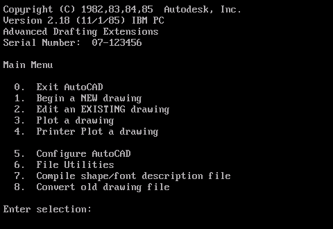
Before you could start drawing or have access to any interface elements, customization or programming, you had to pass this virtual gatekeeper. This persisted long after most applications had discarded this approach, and it made AutoCAD look rather old-fashioned. Then, in 1992, Release 12 arrived, which discarded this menu. It just threw you into the drawing editor at startup. You could do what you wanted from there, no gatekeeper required. The masses rejoiced, because this made perfect sense.

Later, in AutoCAD 2000i, Autodesk had apparently forgotten what a terrible idea it was to have a gatekeeper and reintroduced one. A pretty awful one. Slow, ugly, obstructive, unconfigurable and programmed using entirely the wrong tools, it was an excellent example of how not to do an interface. Despite many complaints, it remained in place until AutoCAD 2004, when Autodesk regained its senses and discarded it again, to near-universal applause.

In order to prove that Autodesk’s corporate amnesia on this matter was a permanent condition, Autodesk would flip-flop several times over AutoCAD startup screens. Every time, the new workus-interruptus device was introduced with a fanfare, until a bit later when it was unceremoniously discarded. In some cases, the unlamented former best-thing-ever was replaced immediately by another, without even a single unobstucted release inbetween. I won’t bore you with the whole saga, but will instead take you forward in time to one step before what we have now.

AutoCAD 2015

AutoCAD 2015 introduced a thing called the New Tab. Start up AutoCAD and you would be presented with something like this.

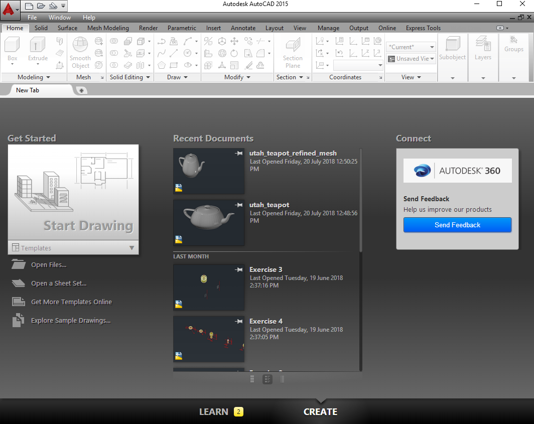
To convince AutoCAD that you don’t want to see this, set the system variable STARTUP to 0 (the default is 3). (Note: the STARTUP system variable dates back to AutoCAD 2004, but its function has changed over the years). Assuming you have specified a default template file, the next time you start AutoCAD you will be placed straight into the drawing editor, ready to work.

If you decide you want to see the New Tab after all, you can always use the NEWTAB command to invoke it directly.

But wait! That’s not the end of the story. If you close the last drawing tab without closing AutoCAD, the New Tab will appear again. If you don’t want the delay associated with this (and in some environments that delay can be 30 seconds or more), you may wish to disable it altogether. To do this, set the NEWTABMODE system variable to 0 (the default is 1). Once you do this, not only will you not see the New Tab accidentally, you’ll also not be able to get to it intentionally, because the NEWTAB command will be disabled.

With NEWTABMODE=0, if you close the last drawing tab, you will be placed in a blank grey screen with very limited functionality, as in previous releases. If your menu bar is turned on (MENUBAR=1), a set of three pull-down menus (File/Window/Help) is visible.

AutoCAD 2016 to 2019

In AutoCAD 2016, the New Tab was tweaked and renamed. It became the Start tab. This was pretty much the same thing, but of course the commands and system variables changed. One thing that didn’t change was the STARTUP system variable, which you still set to 0 to go straight into a drawing.

One difference is that the Start tab is still displayed in the list of tabs even with STARTUP=0. Unlike AutoCAD 2015’s New Tab, the Start tab does not include an X to allow you to close it. Instead of the NEWTAB command, you use the GOTOSTART command to switch to the tab that’s already there.

To make to Start tab go away completely, you need to set the STARTMODE system variable to 0. With this done, you have the same situation as AutoCAD 2015 with STARTUP=0 and NEWTABMODE=0. You still need to configure your desired default template, of course.

While we’re still on AutoCAD, I should mention that there’s a command-line switch (i.e. it can be used in your startup shortcut) called /nologo, which prevents AutoCAD showing its logo on startup. I haven’t discerned any performance benefit in doing so, so I don’t bother. (Edit: YMMV – see comment below). You can also specify your startup template using the /t command-line switch.

Edit: I have covered /nologo’s effect on performance in more detail in the post A & B Tip 3 – benchmarking – /nologo or no?

BricsCAD

What about BricsCAD? Well, it has its own startup screen, but it’s not part of the drawing tab interface.

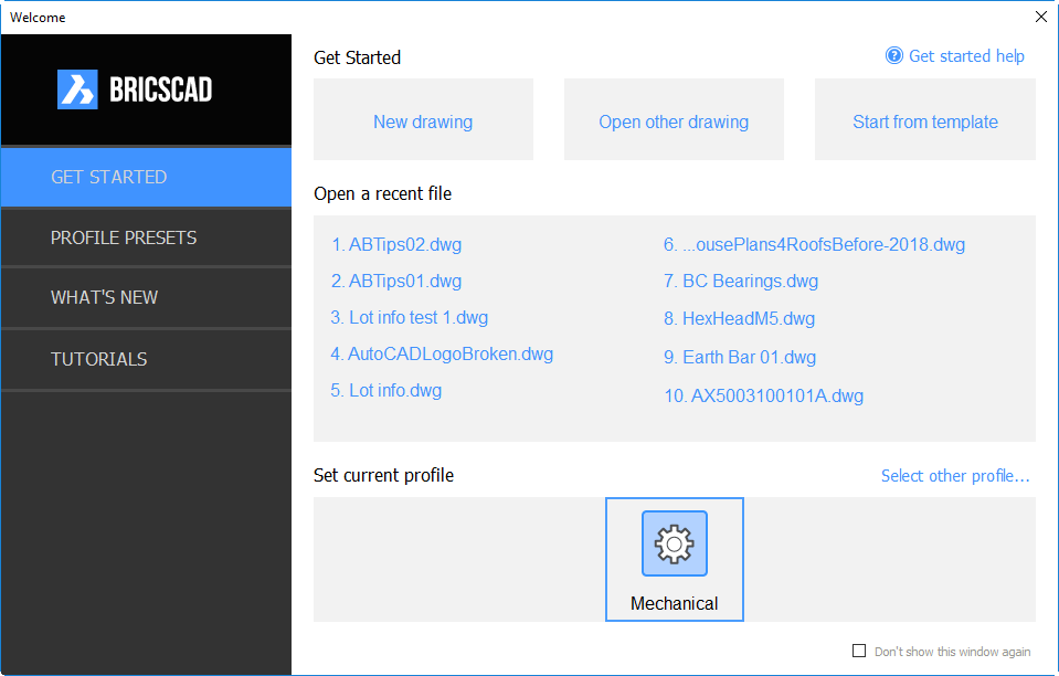
Like most things in BricsCAD, its faster than AutoCAD’s. It’s simpler, smaller and yet provides more functionality. For a brief overview on how it works, see Heidi Hewett’s post BricsCAD Journey – Part 3: Welcome to BricsCAD.

While I still prefer to work ‘raw’, I find the BricsCAD startup the least offensive of any I’ve used. I actually have a use for some of its features, particularly when setting up profiles, and so don’t turn it off until I get into real production mode with a new release. Then I make it go away.

It’s easy enough to turn off, using the Don’t show this window again toggle at bottom right. This is equivalent to setting the system variable GETSTARTED to 0 (the default is 1). That’s it. If you change your mind later, just set GETSTARTED back to 1.

What happens with GETSTARTED=0 is determined by the STARTUP system variable. If STARTUP=1 then the Create New Drawing wizard is launched:

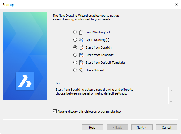
You probably don’t want this either, so set STARTUP to 0. As in AutoCAD, you’ll want to ensure your default template drawing is specified so you go straight into a blank drawing. If you don’t do this, BricsCAD displays the Select Template dialog which you probably also want to avoid.

The default template drawing is defined by the BASEFILE system variable. You can set this system variable directly, or through SETTINGS > Program Options > Files > Templates > Template.

Summary

AutoCAD 2015

STARTUP = 0
NEWTABMODE = 0
OPTIONS > Files > Template settings > Default template filename for QNEW > [your template]

AutoCAD 2016 to 2019

STARTUP = 0
STARTMODE = 0
OPTIONS > Files > Template settings > Default template filename for QNEW > [your template]

BricsCAD

GETSTARTED = 0 or SETTINGS > Program Options > User preferences > Get Started
STARTUP = 0 or SETTINGS > Program Options > User preferences > Startup
BASEFILE=[your template] or SETTINGS > Program Options > Files > Templates > Template > [your template]

Adding Express Tools to BricsCAD

If you’re evaluating BricsCAD to replace AutoCAD, you might be put off by the apparent absence of the Express Tools. Don’t be.

First, some express tool commands have been added to BricsCAD as native commands, such as OVERKILL and TXTEXP.

Next, the Express Tools menu can be added, thanks to a free add-on by Martin Drese (CADwiesel). Here’s the step-by-step process:

  1. Go to the Bricsys Applications page.
  2. Start typing “EXPRESS” into the search box. You should be pleasantly surprised to discover that by the time you’ve typed four characters, what you are chasing will already be displayed for you:
     
  3. Click on the Express Tools box, turn on the checkbox and then pick Download.
  4. If you’re not already signed in with your Bricsys ID at this time, you’ll be prompted to do so. You should have created this ID when you downloaded the main product.
  5. The download (a straightforward one; no nasty download managers involved) is a 3.6 MB zip file. Unzip this to a location of your choice.
  6. As described in the file Install Notes Express Tools for Bricscad V18.pdf, copy the Express folder to the BricsCAD installation folder (e.g. C:\Program Files\Bricsys\BricsCAD V18 en_US). You’ll need admin access for this step.
  7. Add that location (e.g. C:\Program Files\Bricsys\BricsCAD V18 en_US\Express)to the BricsCAD search path (Settings > Program Options > Files > Support files search path).
  8. If you already have a file called on_doc_load.lsp in your search path (this is the equivalent of acaddoc.lsp), then add this line to it:

    (load “Acetutil.des”)

    If that file doesn’t already exist, you can just copy the one from the unzipped location to anywhere in your search path (e.g. the path you just added – C:\Program Files\Bricsys\BricsCAD V18 en_US\Express).

  9. Close and restart BricsCAD.

This is more involved than your typical AutoCAD app store installation, but as a CAD Manager I do like the fact that these are straightforward steps that I can automate in a custom environment such that the users have no need to get involved.

The end result is a Pull-down menu (if you have that turned on – MENUBAR 1 if you don’t) that will be familiar to you:

There are also four toolbar menus:

If you’re using a ribbon and don’t want to see toolbars, substantial manual effort is required to add Express Tools to the ribbon interface. If you are interested in me doing a further post explaining how this is done, please add your comments to this post.

Most of these tools will work with all BricsCAD variants. Some of them require OpenDCL support which is not available in the Classic version, so you’ll need a minimum of BricsCAD Pro (that’s the second level) for complete functionality.

It’s worth noting that the various API LISP functions (acet-xxxx) that are added to AutoCAD by the Express Tools are also there in BricsCAD. Unlike AutoCAD, they are native functions; they can be relied on to be there in BricsCAD, regardless of whether or not the Express Tools add-on is installed as described in this post.

Also unlike AutoCAD, the functions are supported. If there are any problems, you can report them (with, in my experience, a reasonable expectation of them being fixed in a short timeframe by Torsten Moses), rather than being fobbed off by an uninterested Autodesk.

If you go back to step 2 above, see the box that says LISP Developer Support Package (LDSP)? If you code in LISP (with or without BricsCAD), I suggest you download that package. Among many other things, it documents the acet-xxx functions.

Edit: I should point out that R.K. McSwain covered much of this ground earlier this year.